|
||||
 |
||||
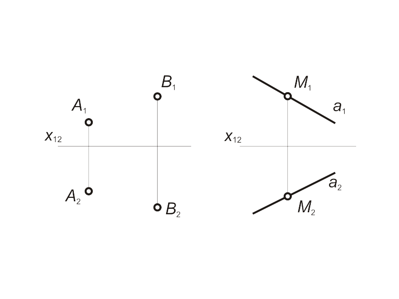
The straight line in common case models as a pair of points (fig.1.13 а) or a pair of straight lines (fig. 1.13 б). The straight line, that is not parallel or not perpendicular with the planes of projections is called as the line of general position. Task # 1.1 Describe the model of an arbitrary point М, that is in incidence with the line a. The algorithm: 1. Let us declare an arbitary point M1 at the line a1 (fig. 1.13 b). 2. Draw a linkage line over the a1 and define the cross point of this line with the second projection a2. This defines the second projection М2 of the point М. |
Fig 1.13 a, b |
|||
The straight lines of special order. The projective lines are lines, that are in incidence with one of the projection center point. In this case one of line's projections maps as a point. (fig. 1.14). |
Fig 1.14 |
|||
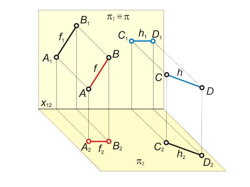
2) Lines of level Lines of level are lines, that are parallel with one of the projection planes. The line f(f1, f2), that is parallel with the plane π1, is called frontal. The second projection of frontal is parallel with a projection axis (f2 || x12) (fig. 1.15). The line h(h1, h2), that is parallel with the plane π2, is called horizontal. The first projection of horizontal is parallel with a projection axis (h1 || x12). |
Fig 1.15 a
Fig 1.15 b |
|||
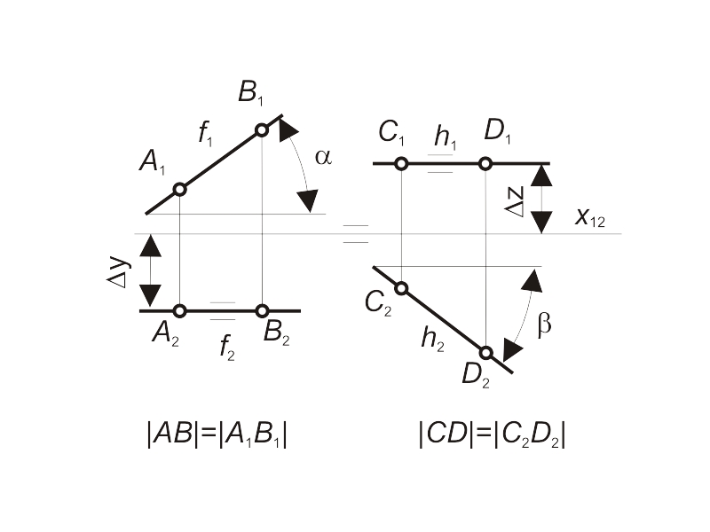
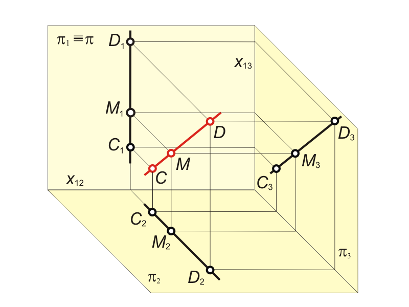
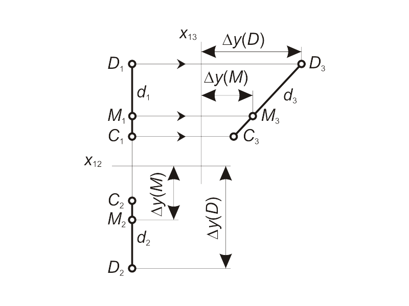
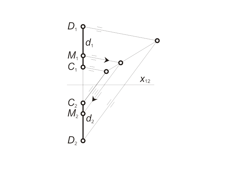
Any segment of a straight line (in the first field in the case of frontal and in the second field in the case of horizontal) projects to a line of natural length. Moreover, the first projection of frontal f1 and the second projection of horizontal h2 define an inclination angles among this lines and projection planes π2(α) and π1 (β) correspondently, but ∆y and ∆z define the distance between f and h and projection planes: ∆y = | f , π1|, ∆z = | h, π2 |. The line d, that is parallel with the projection plane π3 (π1 ⊥ π3 ⊥ π2), is called as profile line (fig. 1.16 а). |
Fig 1.16 a
Fig 1.16 b
Fig 1.16 c |
|||
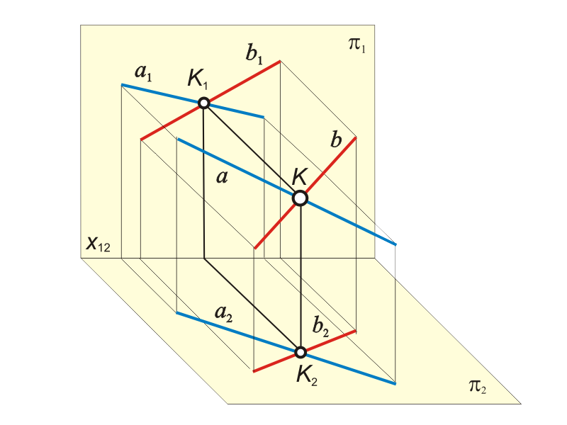
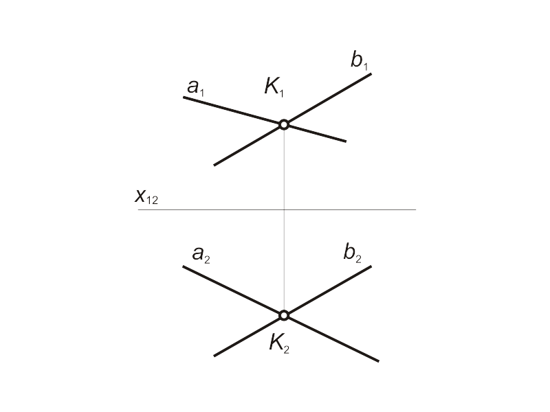
Crossing lines The projections of crossing lines interersect each other in the point, that is the projection of point of initial lines crossing (fig. 1.17). |
Fig 1.17 a
Fig 1.17 b |
|||
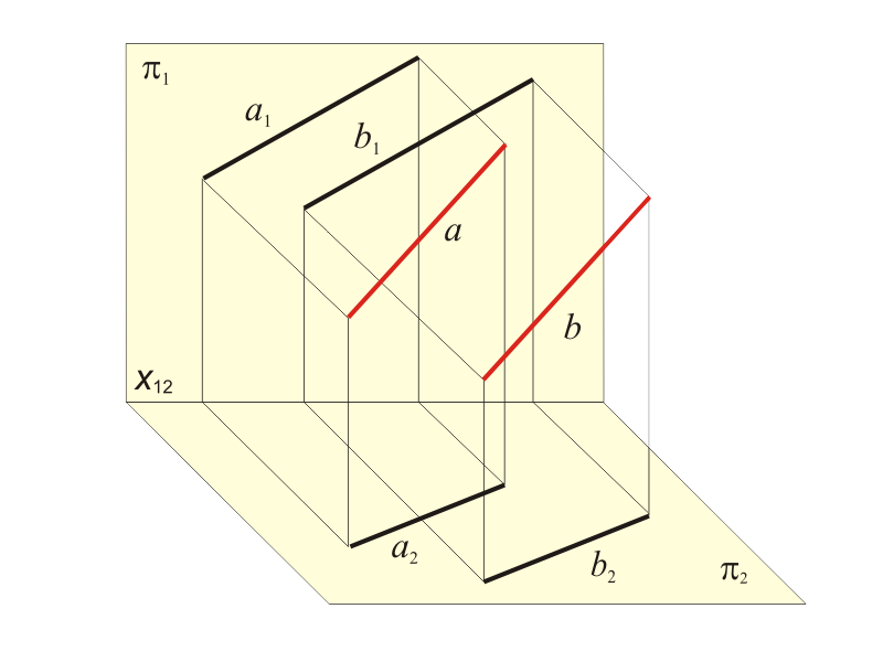
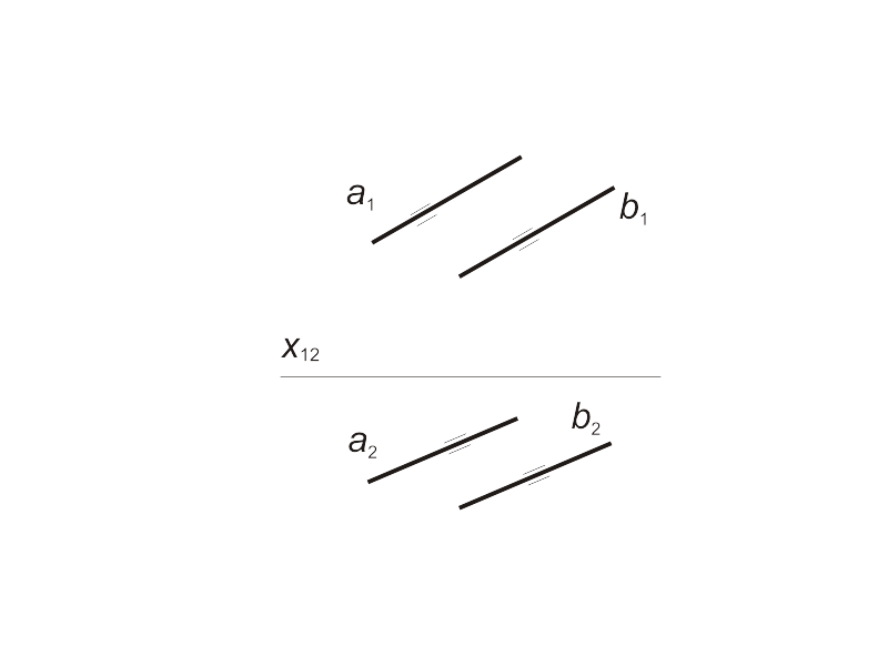
Parallel lines The projections of parallel lines are parallel with each other (fig. 1.18). |
Fig 1.18 a
Fig 1.18 b |
|||
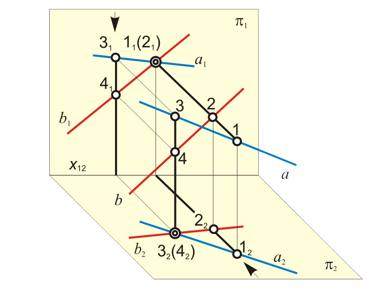
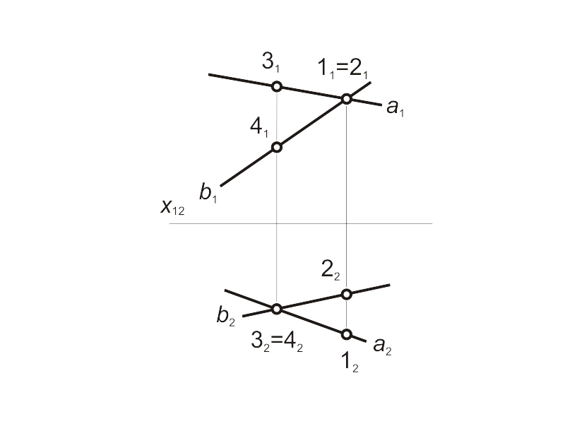
Skew lines The projections of skew lines intersect each other in the point, which is the projection of concurrent points, coincident with this lines (fig. 1.19). It is possible to conclude, estimating the positions of horizontal projections 12 and 22 of concurrent points 1 and 2, that the line b is behind the line a. Estimating the positions of frontal projections 31 and 41 of concurrent points 3 and 4 it is possible to conclude, that the line b is below the line a. |
Fig 1.19 a
Fig 1.19 b |
|||