|
|||
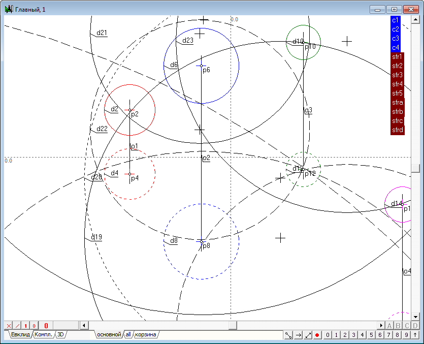
Let's construct the sphere, passing orthogonal to four given spheres. The problem is reduced to solving the following subtasks:
- constructing a radical planes for three pairs of initial spheres; |
|||
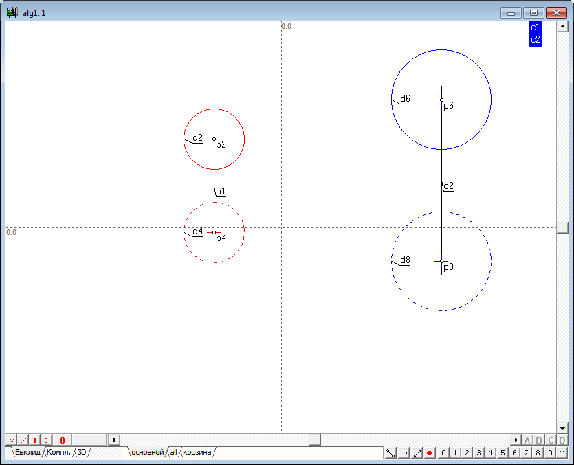
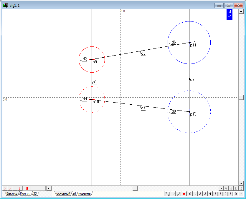
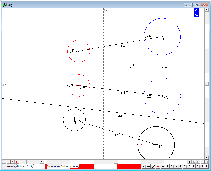
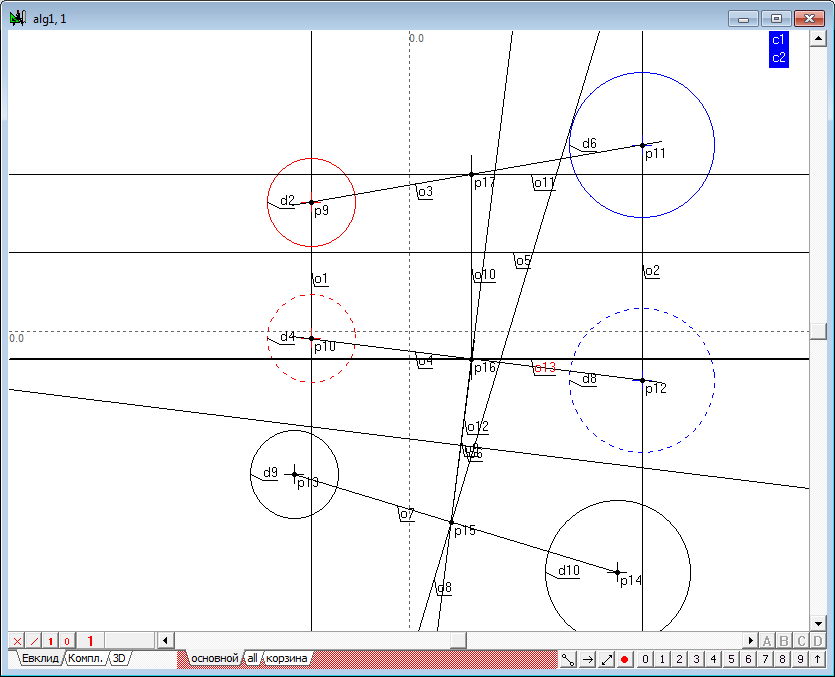
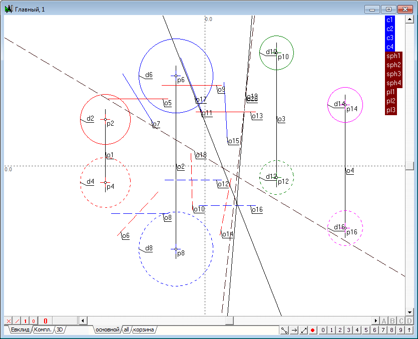
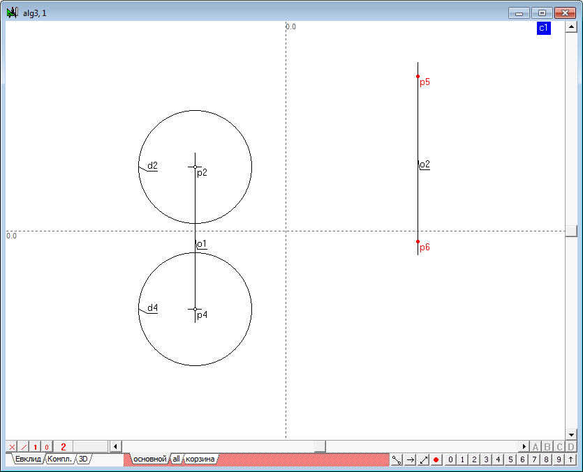
| 1 | Begin to implement the algorithm for solving the problem. Open a new project and define the model the four spheres in the window of the main algorithm of. Use a Free circle tool to do it. Before the formation of the spheres make sure that, the indicator of the number of projections is set to 2. If it is not, then, placing the cursor over this indicator, right-click to invoke a context menu where you can select and set the desired value. |
||
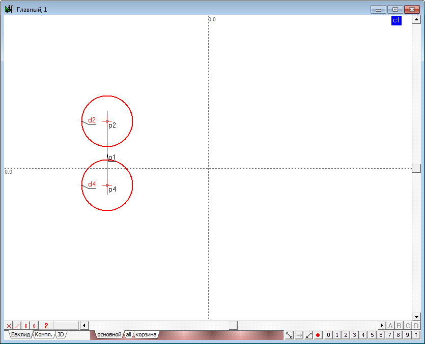
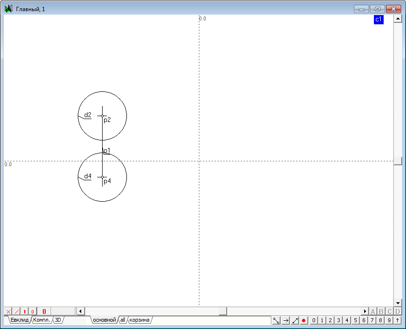
| 2 | Place the cursor at any position on the screen holding the Ctrl key, then drag out a circle of desired size. After releasing the left mouse button a model of a sphere, consisting of two circles whose centers are on a single line, would be formed in a viewport. The radii of the two circles interlinked through a common radius of the specified variable c1. As a result, the radius of the sphere can be controlled with a shaper, capturing any of them formed circles, the radius of the remaining circumference will vary in accordance with variation of the radius of the active circle. |
||
 |
|||
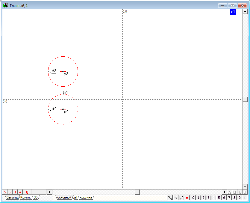
| 3 | After the formation it makes sense to assign to the lines color, which will distinguish it from other models present in the drawing. To do this, select both circles and assign a common color to them.
To determine the difference of the model projections the circle to be regarded as a horizontal projection, to be in a different drawing style in comparison with front projection. For this purpose it is necessary to allocate and assign dashed style to it.
|
||
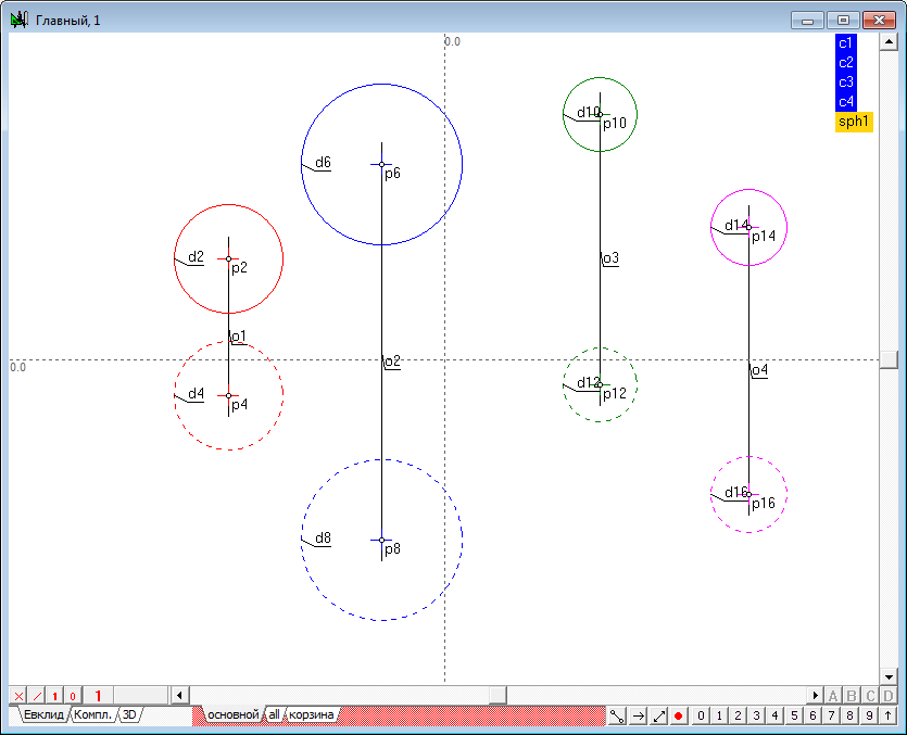
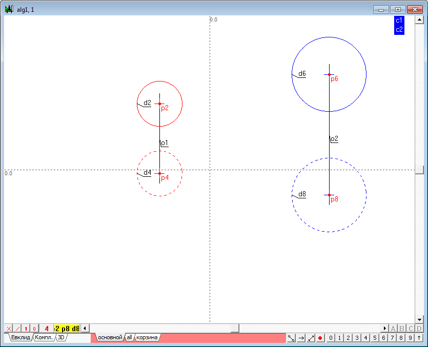
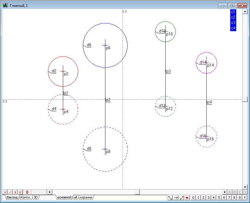
| 4 | Similarly we define the model of three more spheres and change the values of attributes of these models according to previously proposed scheme. |
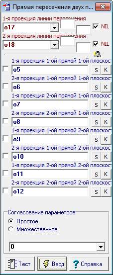
||
 |
|||
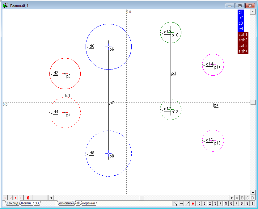
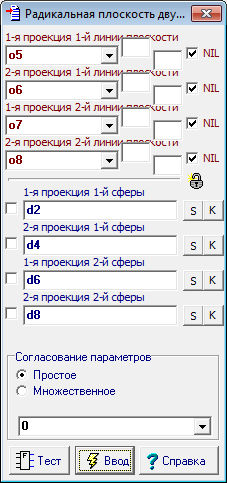
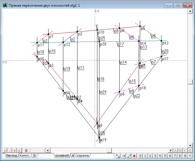
| 5 | To facilitate future work it will be useful to implement semantic grouping of objects models to understand the fragmented geometric images of a named set, simulating a single object in three-dimensional space. Highlight sequentially the first and second projections of the first sphere (the order is important!), hold down the Shift key and press the keyboard key with a capital Latin letter G. This command is designed to assign a name to the group of selected objects. In the on-screen window, specify the name of the group, for example, sph1.
A similar groups should be created for all other spheres.
|
||
| 6 | Let's build the radical plane of two spheres. Implement the solution of the problem in a new window, which will create a new algorithm by pressing the key combination Ctrl+Alt+N. The algorithm will build a model of any two spheres in new window, as well as in the main window.
The idea of the algorithm is the following. Suppose there we have two circles. Connect their centers and construct the radical axis. It is clear that the radical axis is perpendicular to the line connecting the centers of the original circles. Put this flat scheme in three-dimensional space and carry out its rotation by 180 degrees around the line axis connecting the centers of the circles. When the rotation axis goes into itself, while the circles form two spheres. The radical axis, spinning in space, will set the plane that will be the radical plane of two formed spheres. Consequently, the spatial problem can be reduced to flat, if you convert the original projection so that the radical plane would take a projecting position. This transformation is easy to implement, if the line joining the centers of the two spheres converts to level-line in the new system of projections. In this case, the plane perpendicular to this line will be represented in the form of a straight line in the field of projections, where the level-line is displayed in natural size. In this field of projections the radical plane can be constructed as the radical axis of two circles by using the standard functions of the system Simplex. Finding the point of intersection of this plane with the line connecting the centers of the spheres in this field, it is not difficult to determine the position of projection of that point in the source fields, restoring lines of communication from the known projection of additional fields in the source fields of projections. Now one should draw the plane perpendicular to the line connecting the centres of the original spheres through the obtained point. It is known that such a plane can easily be determined with the aid of two level-lines of frontal and horizontal, which pass through the point, where the projection of level-lines, which are depicted in natural size, should be held perpendicular to the corresponding projections of the line, connecting the projection centers of the initial spheres. This set of lines is the determinant of the required plane. |
||
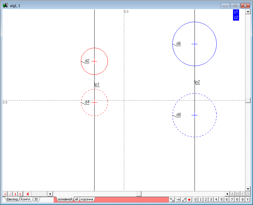
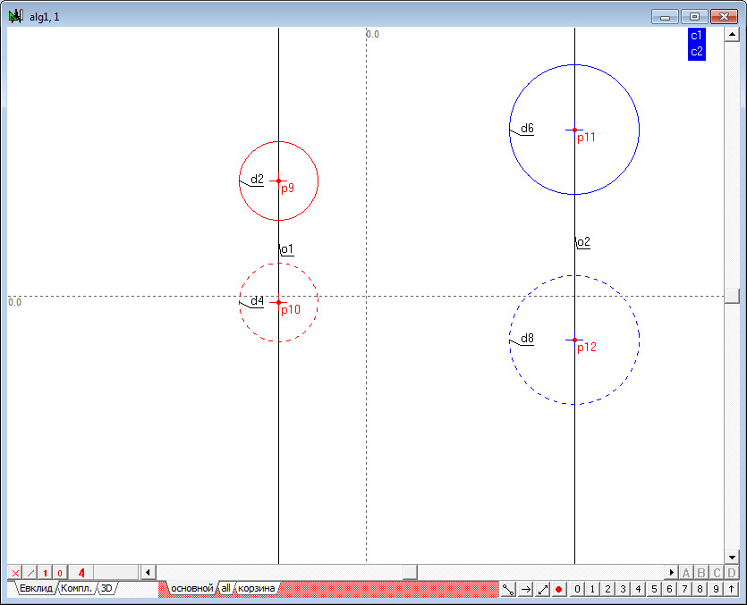
| 7 | Begin to implement the algorithm. The first thing to do is to determine the position of points of centers of the initial spheres. Despite the fact that the points corresponding to the centers that already exist in the drawing, they can not be used to build the algorithm. This is due to the fact that the points are the predecessors of the circles (not Vice versa). As the transfer values in the algorithm will be implemented by overriding the values of the circles, this action may not affect their ancestors, resulting in points, to set the centers of the circles will not change and will not correspond to the actual values of the positions of the centers of the spheres. As a result, we will need to re-find points of centers of the circles to make them dependent on them and continue to refer to them in the implementation of the remaining part of the algorithm. So select the points p2, p4, p6, p8 and transfer them to the layer the basket layer.
|
||
| 8 | Hold down the Shift key, select one of the circle d2, d4, d6, d8 and press the keyboard key with the letter c. This will point depending on the position of the circles.
|
||
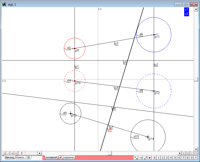
| 9 | Connect the respective projection centers of the straight lines and assign them the attribute of limitlessness.
|
||
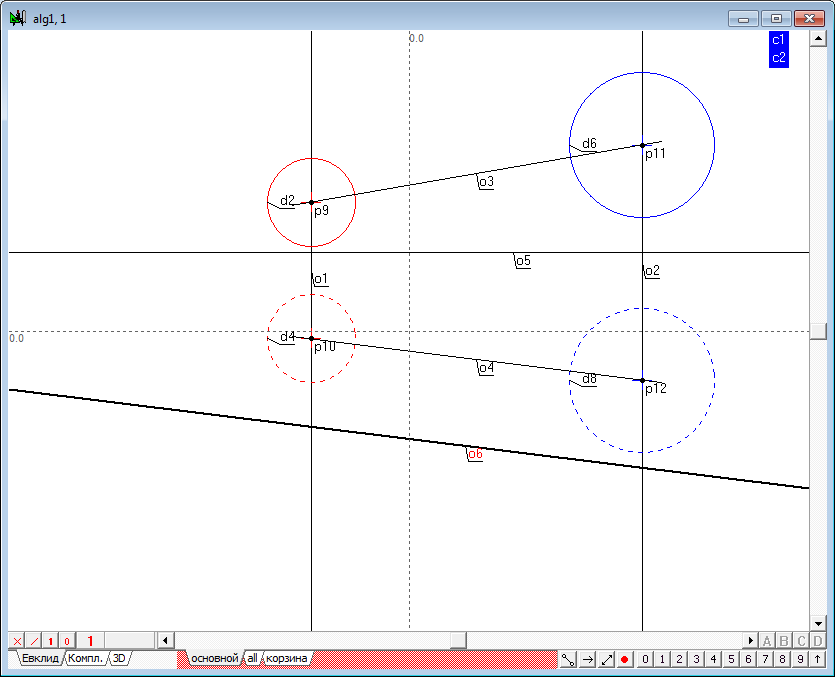
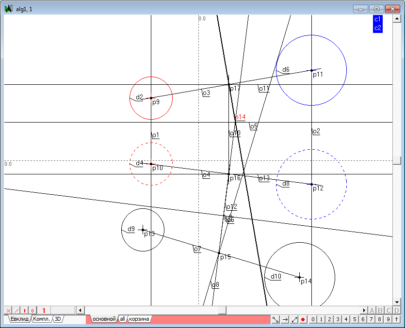
| 10 | To build additional fields of projections define the reference axis of the projection as a horizontal line o5 carried out in a random location in the drawing. To do this, remove all the possible allocations of the objects and press on the keyboard with Latin character h.
An additional axis will hold the second in parallel projection the lines connecting the centers of the spheres. To do this, select the line o4, take the cursor slightly below the line and click on the keyboard with Latin character o. This command allows to build the required line. If necessary, the position of this line you can adjust the shaper.
|
||
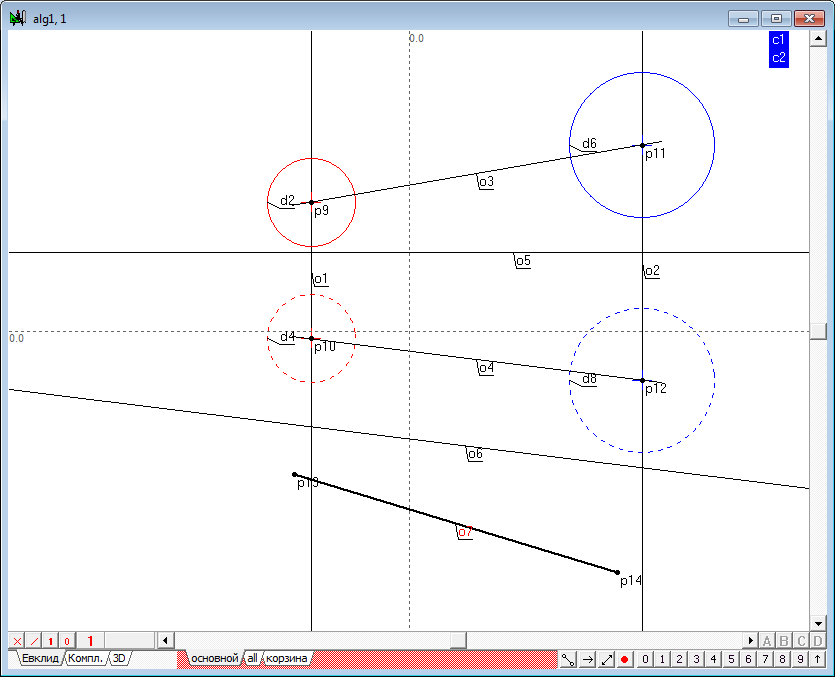
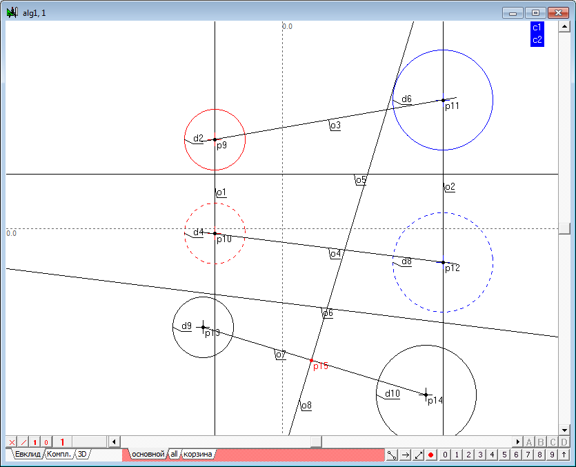
| 11 | Now we construct the additional projection of the centers of the spheres. Twice perform a transformation, use the function point of the replacing planes of projection. The result is two points (p13, p14), through which draw a straight line o7.
The lines o4 and o7 model the level line in the new system, projections, and line o7 displays a line connecting the centers of the initial spheres, in natural size. Therefore, in this field, the radical plane is modeled by the radical axis of two circles - the respective projection of the spere contours. |
||
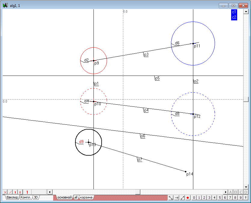
| 12 | Construct contours of spheres in the third field. To do this, hold down the Shift key, select successively the point p13 and the circle d4, then press the keyboard key with the Latin character d. The third projection of the first sketch of the sphere is built now.
Similarly, we construct the second contour of the sphere.
|
||
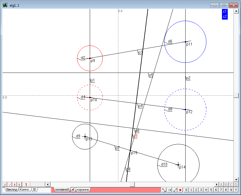
| 13 | Hold down the Shift key, select successively the circumference of d9 and d10. Clicking on the button with a Latin symbol r, construct the radical axis of two circles o8.
|
||
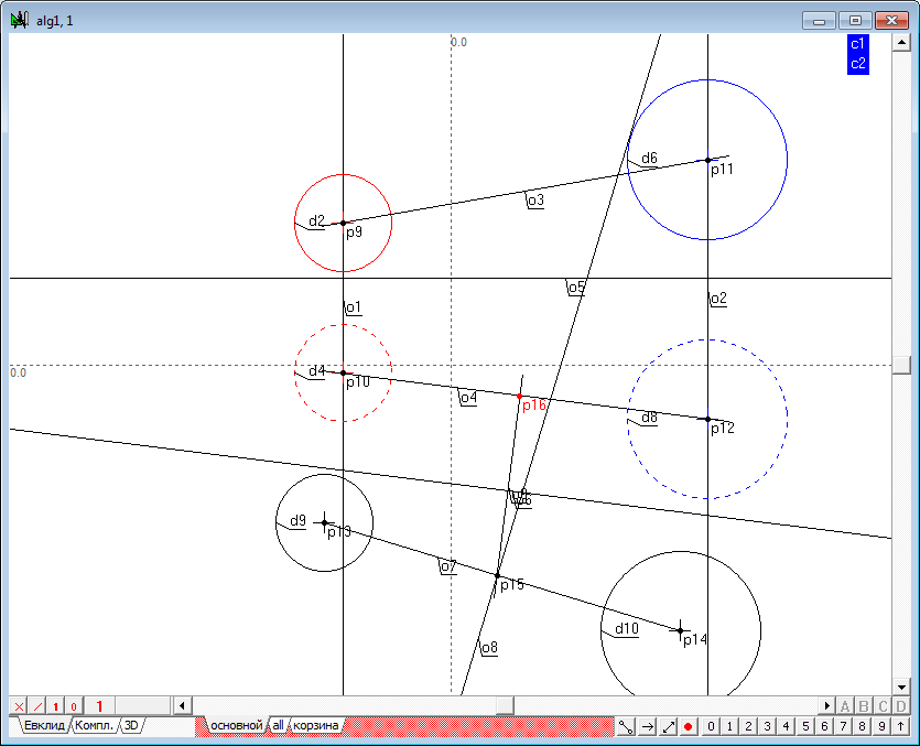
| 14 | Determine the intersection of the radical axis o8 with a projection of a connection line of centers of the initial spheres, the point p15.
Since the point of intersection of the radical plane and the line connecting the centers of the initial spheres, belongs to this line, the projection of the point in the source fields are by restoration of communication lines in these fields from the known projection of this point. To construct a second projection, hold down the Shift key, select the point p15 and a straight line o6, and then press the key with the Latin o. The result will be a built connection line between the third and second fields - direct o9.
The second projection point (p16) determine as the point of intersection of lines o9 and o4.
Draw the communication line from the second field to the first one. To do this, press the key with the Latin symbol v (because the source point is already selected), determine line o10 and cross it with the first projection of the line connecting the centers of the spheres (o3). Thus, the spatial position of the point (p17-p16) of intersection of the line connecting the centres of the original spheres, radical plane, is defined.
|
||
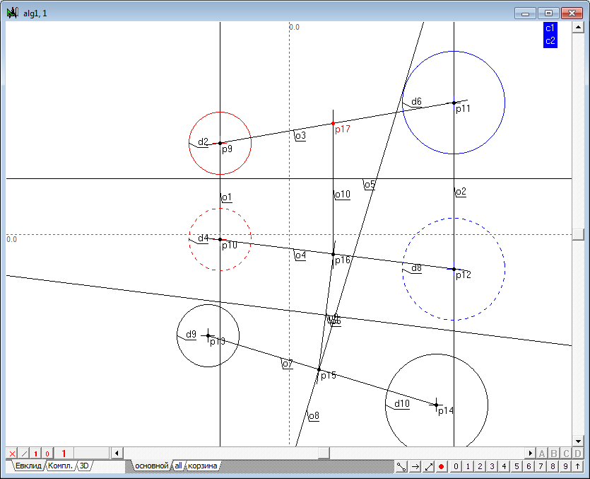
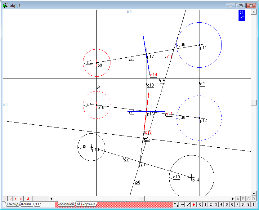
| 15 | We have to draw through this point a plane perpendicular to the line joining the centres of the original spheres. To build this horizontal plane, select the point p17 and press the key with the Latin character h. Get direct o11.
Next, hold down Shift, select the point p16 and o4 line, and then press the key with the Latin o. Get line o12. Direct o11 and o12 model a one of the plane lines, which is perpendicular to the original straight line.
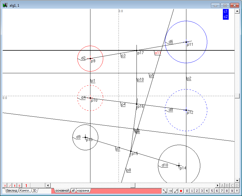
To build the frontal of the plane that is perpendicular to the line, select the point p16 and press the key with the Latin character h. Get line o13.
Next, hold down the Shift key, select point p17 and direct o3, and then press the key with the Latin o. Get line o14.
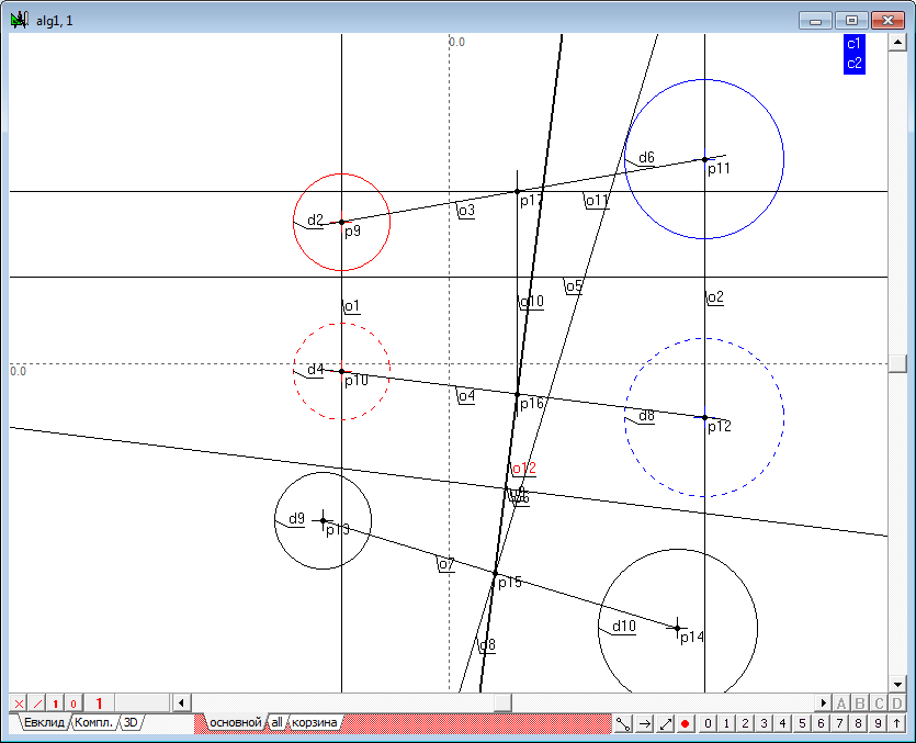
Lines o13 and o14 simulate a second straight line of the plane, which is perpendicular to the original straight line. Now we have two intersecting straight lines perpendicular to given one. This implies that a plane determined by these lines are also perpendicular to the baseline. The radical plane is determined. For the convenience of use of the output of this algorithm, assign the respective projections of the lines defining the radical plane, of a distinctive colour, limit the visual length of these lines by selecting them and clicking on the key with the number 9, and set the line style for the second projection of determined objects.
|
||
| 16 | Form the interface of the created algorithm. Hold down the Shift key, select sequentially the first and second projection sketches of the first sphere is the circumference of d2 and d4, and then the first and second contours of the second projection of the sphere - circle d6 and d8. Triggering a right-click context menu select - Assign "d2,d4,d6,d8" as the input of the algorithm. In the text field of the appearing dialog, enter the following parameter names: 1st projection of the 1st sphere; Now select sequentially the first and second projections of the first line of the radical plane - lines o11 and o12, and then the first and second projections of the first line of the radical plane - lines o14 and o13. Triggering a right-click context menu select - Assign "o11,o12,o14,o13" as the output of the algorithm. In the text field of the appearing dialog, type the following parameter names: 1st projection of the 1st line o the plane; We have to give the name of the created algorithm. Call the dialog box to create algorithm's interface by pressing the key combination Alt+A. In the name field of the algorithm enter the text: the Radical plane of two spheres. |
||
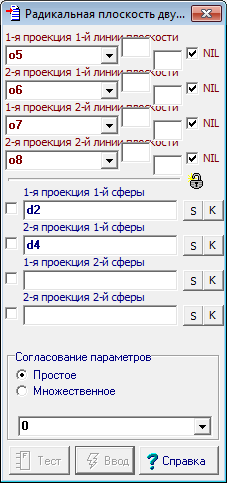
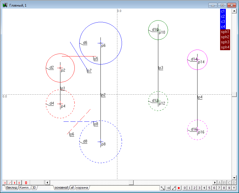
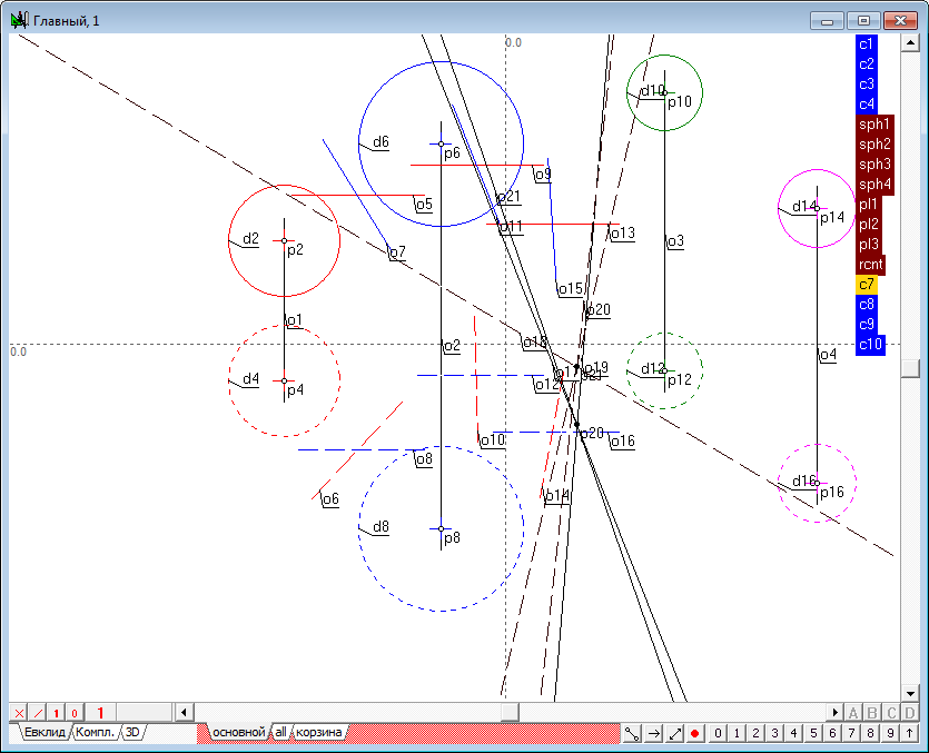
| 17 | Now it is time to determine radical plane for the three pairs of spheres presented by the groups: sph1-sph2; sph1-sph3; sph1-sph4. Pass to the main algorithm by clicking in its window and call the menu item Relations/Procedures/Radical axis of two spheres. The dialog that appears to construct the radical plane contains four input parameters. Of course, the input of these parameters can be done by pointing to a corresponding geometric image in the drawing of the main algorithm. But since the objects are combined into groups, this operation can be performed in an alternative way. Point out the cursor on a tag group named sph1. As a result, the names of the two objects, combined the group will be sequentially substituted into the text fields of the dialog box.
Clicking on a tag with the name of the group sph2 will allow to create input parameters.
It should be noted that the order of the objects in the group must match the order of the input parameters of the algorithm. Therefore the developed algorithm should take care of the compliance with this order in the formation of groups and lists parameters of the algorithm.
|
||
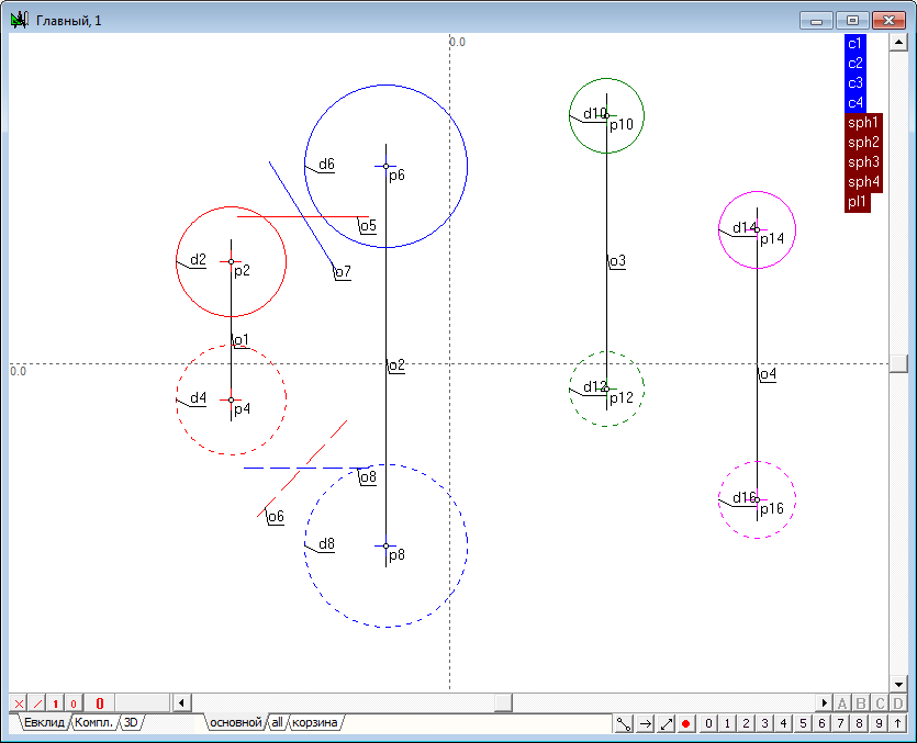
| 18 | Perform the same steps for groups sph1-sph3; sph1-sph4, get images of all three radical planes. Assign groups for the resulting planes. Consistently highlighting the object (or removing the selection from all objects, press the key with the Latin character l, which will select all objects generated by the last command), modeling the first radical plane, press the keyboard key with the Latin symbol G. Specify the group name, for example, pl1.
Similarly, we form groups for the remaining planes - pl2 and pl3.
|
||
| 19 | The solution to the problem of constructing the line of intersection of two planes will perform in strict accordance with the algorithm described in the example, The intersection of the planes.
|
||
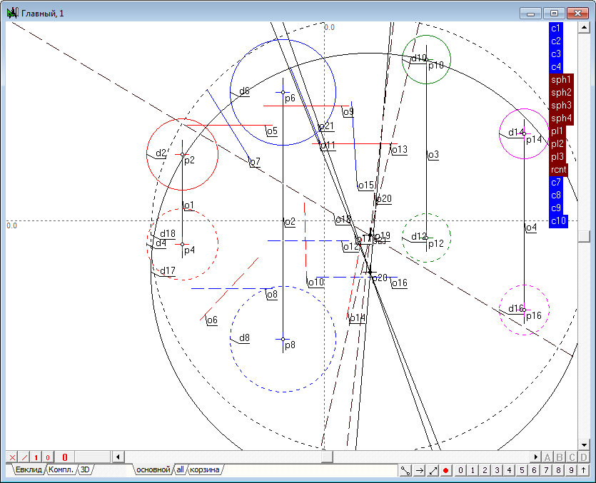
| 20 | Determine the intersection of the first and second radical planes (pl1-pl2). To do this, select the menu item Relations/Procedures/Intersection of two planes. Referring to the group corresponding to the source planes, will form the command and execute it.
Determine the intersection of the first (pl1) and the third (pl3) radical planes.
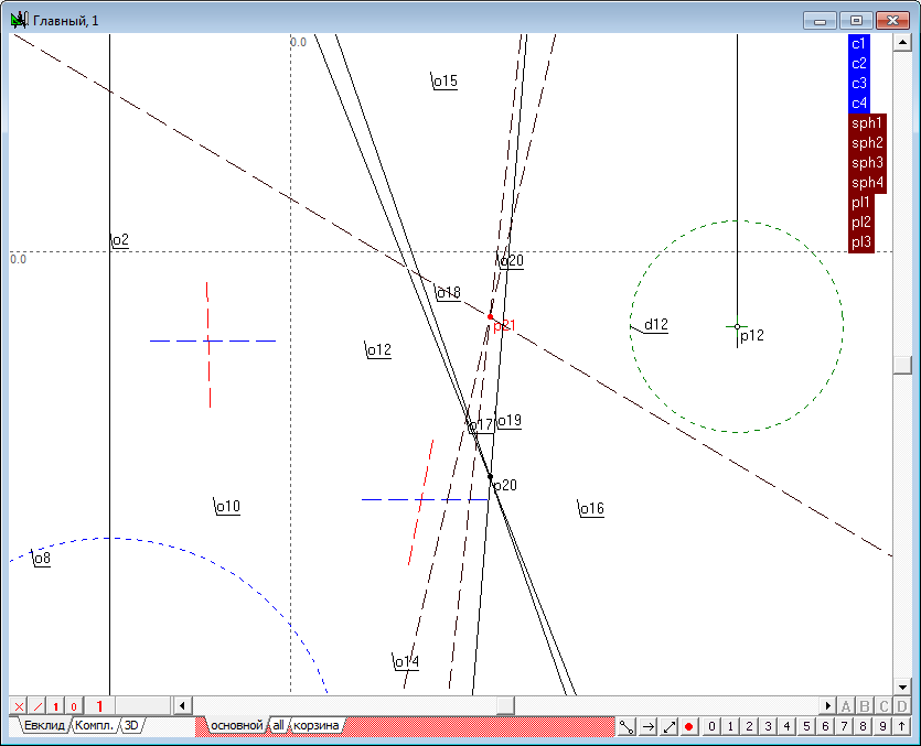
Determine the point of intersection of the respective lines in the first and second fields of projections. Note that the generated points are on the single communication line.
Despite the fact that the decision has been received, it is recommended to ensure that construction of the line of intersection of the planes pl2-pl3 will produce the same result. Thus, the locus of the radical centre of four spheres was found.
|
||
| 21 | To complete the solution of the problem remained to determine the length of the generatrix of the cone is lowered from the radical centre to any of the source fields. Create a new algorithm and set the (free circle tool with Ctrl) and point (deselect any objects and press the key with the Latin symbol v).
|
||
| 22 | Omit tangent from the first projected point to the first projection of the sphere outline. To do this, hold down the Shift key, select successively the point p5, and a circle d2 and press the keyboard key with the letter o.
In accordance with the rules of the sphere simulation, the second projection of the touch point of the image, located on the Prime Meridian, will be found on the second projection of the Prime Meridian. To construct a line of the second projection of the Prime Meridian, select point p4 and put it in the trash layer (see the remark about the centers of the spheres in the task of building a radical plane) by pressing the \ key, determine the center p9 of the circle d4, by selecting it and pressing the key with the Latin character c, and then press the key with the Latin character h (line o5). Keep the selection and holding down the Shift key add point p7 to the selection, then press the key with the Latin character p. Thus, we received a second p10 projection of the touch point of the image, that is omitted from point on the sphere. Build this tangent and determine its natural value. |
||
| 23 | Algorithm for the construction of the true length of the segment has already been considered by us earlier. Recall that to solve the problem you need to set the position of the axis o7 of the original system of projections (arbitrary straight line defined by pressing the key with the Latin symbol h) and the axis o8 of an additional system of projections (i.e. one of the projections (o6) measured in a straight line and parallel to it is straight o8, by pressing the key with the Latin o). Then build additional projection of the points p11,p12, defining the measurement distance o9. The obtained points determine a straight line o9, highlight these points and press Latin character o. The definition of the desired length c2 is carried out by pressing the key with the Latin character l. Highlight contours of the projection sphere and the projections of the point, assign them to the input parameters and specify their names. The only output parameter is the value of c2. Assign it as an output parameter and set up a name - The length of the segment. Pressing the key combination Alt+A, call dialog box for the algorithm adjusting, set up a name to this algorithm - The Length of the generatrix of the cone. |
||
| 24 | Back in the main algorithm to find the desired distances from the radical center to all of the source areas, causing the newly formed function. Make sure that all the found distances are the same.
This should cause the Protocol the values of objects with the key combination Alt+O, and choose the appropriate variables. |
||
| 25 | Complete solution of the problem, highlighting the first projection of the radical center and found the value, then press the key with the Latin character d. The screen will built the first projection of the sphere orthogonal to four given spheres. To perform the second projection of the construct, highlight the point p19 and the value of c7. We will use the same command to construct a second projection of the sphere outline. Change the drawing style of the second projection to the dashed.
|
||
| 26 | Thus, we have obtained an algorithm for constructing a sphere orthogonal to four given spheres. It makes sense to formalize this algorithm as a standalone procedure, suitable for further studies of the properties of a system of four spheres. Select all the objects of the main algorithm is a combination of Ctrl+A and copy them to the Clipboard the corresponding menu item. Confirm that you copied all the objects of the algorithm. Create a new algorithm using the key combination Ctrl+Alt+N and paste the contents of the Clipboard buffer. In the dialog that appears, select the Common insert. |
||
| 27 | Make the algorithm interface. Highlight sequentially the first and second projections of the first sketch of the sphere, then the second, third and fourth. Assign selected objects input parameters of the algorithm. Output parameters indicate the first and second orthographic projection of the sphere. In the settings window of the interface of the algorithm we specify the names of input and output parameters and the algorithm, for example, the Orthogonal sphere of the four spheres. | ||
| 28 | For example, the presence of such algorithm allows, to perform the following interesting construction: we define the four spheres and construct the fifth sphere orthogonal to four given. Having now five spheres will build a new four ones, using as the source indexes: 5,1,2,3
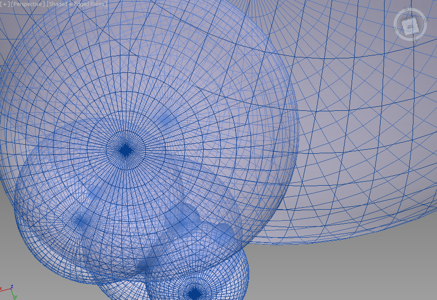
Here is 3d-Studio Max representation of modeled scene.
|