|
||
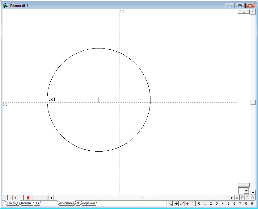
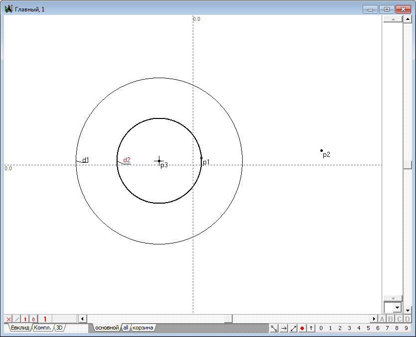
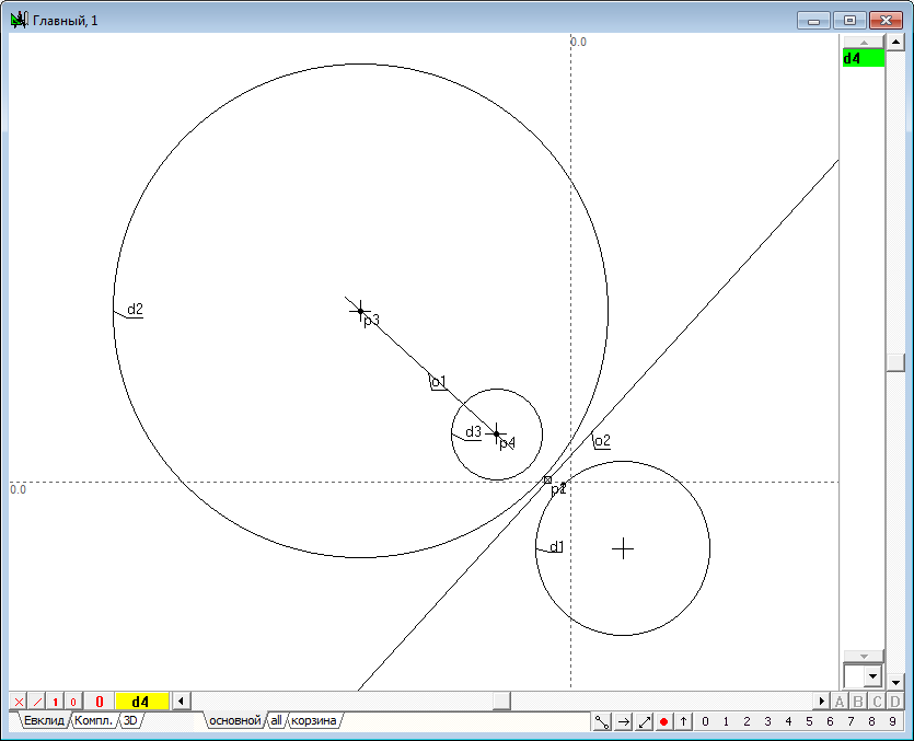
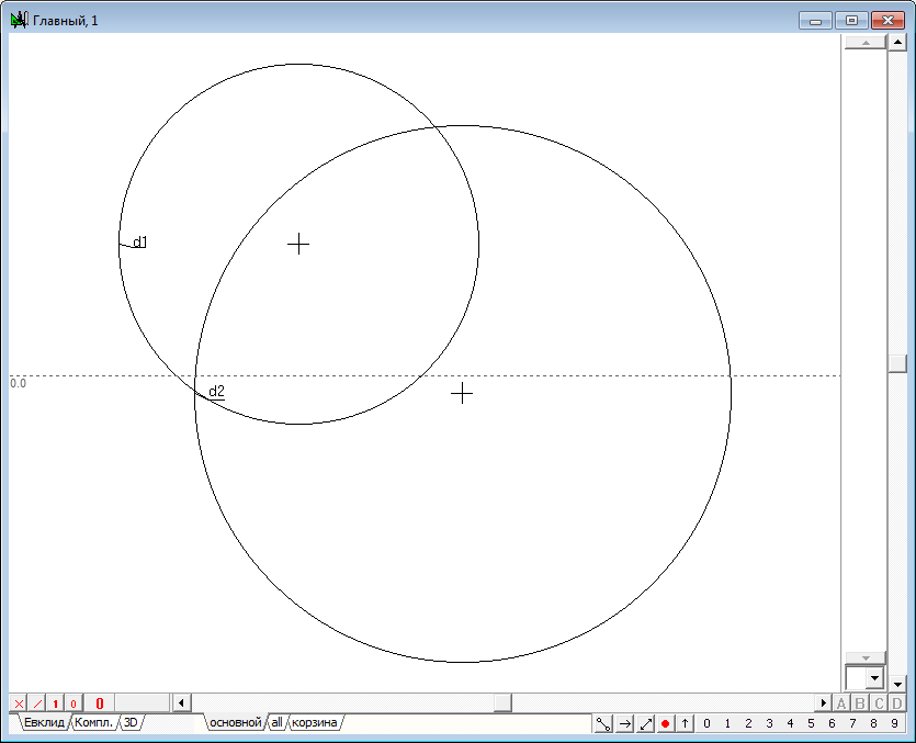
| 1 | Let we assign a circle d1, using the Free circle tool.
Fig. 1 |
|
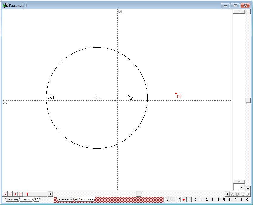
| 2 | Place the point p1 in the internal area of the circle d1 using the Free point tool .
Fig. 2 |
|
|
||
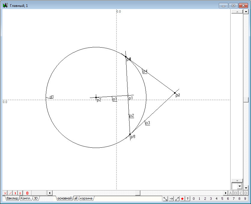
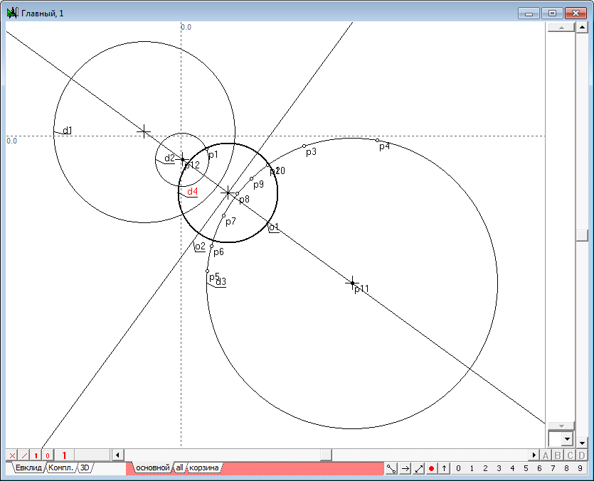
| 3 | Now let's execute the algorithm of finding the image points in the transform of inversion. It consists of the following items: 1. Let we find the center p2 of the circle d1, which we will name the circle of inversion. To do this, select the circle d1 and click on the key with Latin character c. 2. Draw the straight line o1 passing source point p1 and the center p2. To do this, select both points and click on the key with the Latin o, then press the key with digit 8, to change the attribute lines from restricted to incident. 3. Draw perpendicular o2 relative to line o1, passing point p1. To do this hold down the Shift key to add to the selection (lines o1) point p1, then click on the key with Latin character o. 4. Determine the points of intersection of the line o2 and the circle of inversion d1: points p3 and p4. To do this, hold down the Shift key to add to the selection circumference d1, and then press on the key with Latin character p. 5. Disable selection by moving the cursor to the position free from any objects and click on the left mouse button. Now let's draw two tangent lines to a circle d1, passing through the points p3 and p4. To do this, select the circle d1 and point p3, and then click on the key with the Latin o, which will get a tangent o3. Remove it from the selection, then select the circle d1 again, but in conjunction with point p4, and construct a tangent o4. 6. Найдем точку p7 пересечения касательных o3 и o4, для чего выделим их и нажмем на клавиатуре клавишу с латинским символом p. Determine the point of intersection p7 of the tangents o3 and o4. To do this highlight lines and click on the key with Latin character p.
Fig. 3 |
|
| 4 | The resulting point p7 is called the image of a point p1 in the transformation of inversion, induced by a circle d1. Using the shaper, perform some movements of the point p1 in the inner region of the circle d1. The observations for dynamics of constructions, we would find that the point p7 changes its position so that when the point p1 moves to the circle d1, the point p7 is committed to a position coincident with a point p1 that is located on the circle. When the point p1 moves to the center of the circle d1 (point p2), point p7 tends to infinity in the direction of the line segment o1. In the case of coincidence of p1 with p2, the geometric construction can not be performed because of the uncertainty of the position of the straight o1. In this case, the point p1 is displayed on the entire infinity line, however, created algorithm does not support this conversion. And finally, when the point p1 is outside the inner region of the circle, we observe a degeneration of the algorithm due to the fact that the points p3 and p4 of intersection of a straight line o2 and the circle d1 become imaginary and we cannot constuct the tangents o3 and o4 with ordinary means.Therefore, the position of the point p7 becomes impossible. However, it should be noted that the transformation of the point p1 to the point p7 is one-to-one. For this reason, we can assume that the point p1 corresponds to point p7 in the transformation of inversion with respect to the circumference of d1, if construction shown in the drawing to run in the reverse order. It means, that we take as the starting point its analog - point p7, then draw two tangents to the circumference of d1, passing point p7, determine touch points, draw the line, passing this points and find the point of intersection with the line passing through the center of the circle of inversion d1. A transformation in which the corresponding objects pass into each other is called involutive. Combining the original construction wih is opposite version, gets us a total transformation of inversion, which transforms any point in its way, excepting only a few cases: 1. The starting point should not coincide with the center of the circle of inversion; 2. The circle of inversion must have a real radius that is different from zero. |
|
Because the transformation of inversion is quite often used foк solving practical and research tasks, the reviewed geometric construction was put on the basis of the algorithm of the same function of the Simplex - Inversion of the object. Therefore, the fdeermination of the image of the point in inversion can be found in the execution result of one operation without having to perform a "direct" and "inverse" constructions discussed in order to explore the geometric nature of this transformation. However, the function of Inversion allows us to perform transformations in the inversion not only for points but also to other geometric images, in particular, circles and straight lines. These transformations have several interesting properties, which we will introduce in the following experiments. |
||
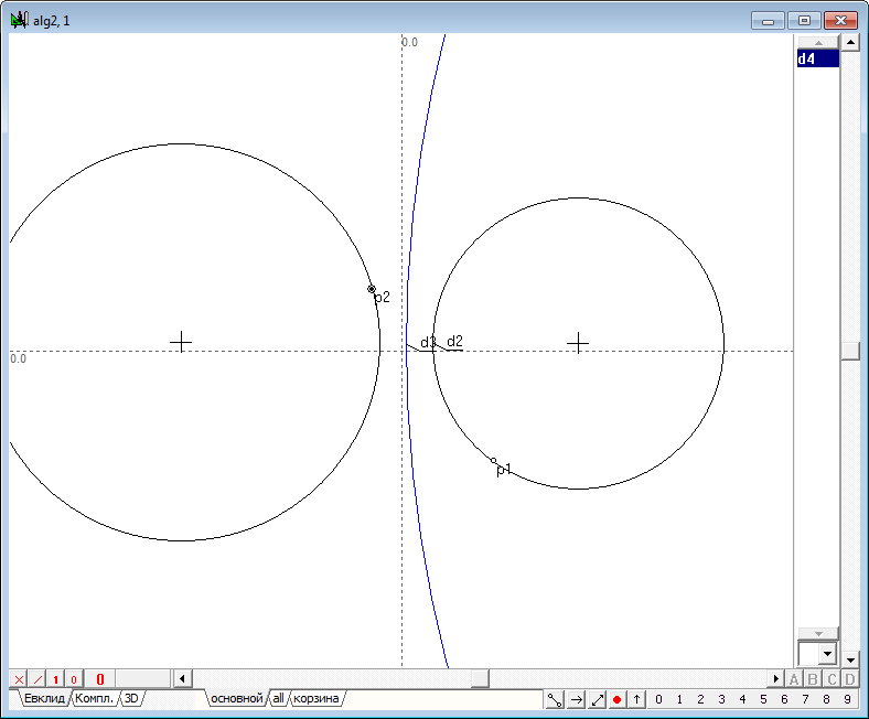
| 5 | So, draw in the area of drawing a circle and place the point p1, for which we look for the image of p2 in the transformation of inversion in relation to the circumference d1. We will fulfill this transformation. To do this, select the first point p1, and then hold down the Shift key to add to the selection the circumference d1. Press on the key with the Latin character " i " (lower case). The result of the command will be appearance of the point p2. "Hooking" the point p1 with a shaper, begin to move it so that its trajectory would be a circle concentric with the circumference d1. It is easy to see that the point p2 will also move along a trajectory - a circle concentric with the circumference of d1, so we can conclude that a circle concentric with the circle of inversion are transformed to the transformation of inversion in a circle concentric with the original (and with the circle of inversion). Разумеется, вручную перемещать точку таким образом, чтобы она строго соблюдала необходимые условия перемещения, достаточно сложно. Поэтому и результат преобразования можно оценить лишь качественно (с грубым приближением). Для того чтобы эксперимент дал более точные результаты, воспользуемся несколькими приемами, позволяющими задать точные перемещения точек на плоскости, а также зафиксировать результаты промежуточных построений. Of course, to move the point manually so that it strictly complied with the required conditions of the movement, is quite difficult. Therefore, the conversion result can be evaluated only qualitatively (rough approximation). In order for the experiment gave more accurate results, we use several techniques that allow to specify precise movements of points in the plane and record the results of the interim constructions.
Fig. 4 |
|
|
||
|
||
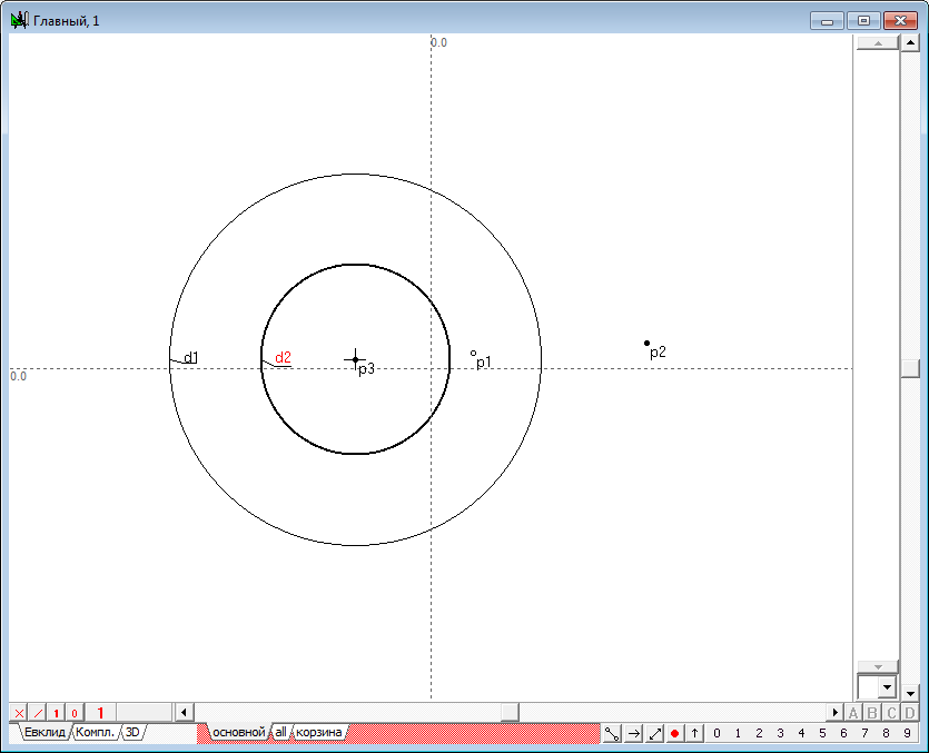
| 6 | In order to "force" the point p1 to move strictly along a circle concentric with the circumference of d1, perform the following steps: 1. Find the center p3 of the circle d1, by highlighting it and pressing on the key with Latin character c. 2. Move the cursor a certain distance from the selected point p3 and press on the key with Latin character d. The result is a circumference d2, concentric with the circumference d1.
Fig. 5 |
|
|
|
||
| 7 | "Hooking" with a shaper point p1 and holding down the Shift key, move a point p1 towards a circle d2 so that it is located directly above the picture of its outline, release the left mouse button and then release the Shift key too. The result of these steps is that the function specifies the point p1 will be automatically overridden. Since releasing the Shift key the point is set to the function Point belongs to the object. In particular, p1 is now owned by circumference d2 with the corresponding parameter position, which was automatically calculated at the time of the operation. Perform the displacement of the point p1 by the shaper. We find that the point p1 should be the circumference and can not take an arbitrary position on the plane. As a result, all objects, dependent on p1, change their position in accordance with the entered positional restriction to the point p1, that allows us to explore the "geometric behaviour" of the point p2 and observe how it moves according to a circular trajectory followed by the moving point p1.
Fig. 6 |
|
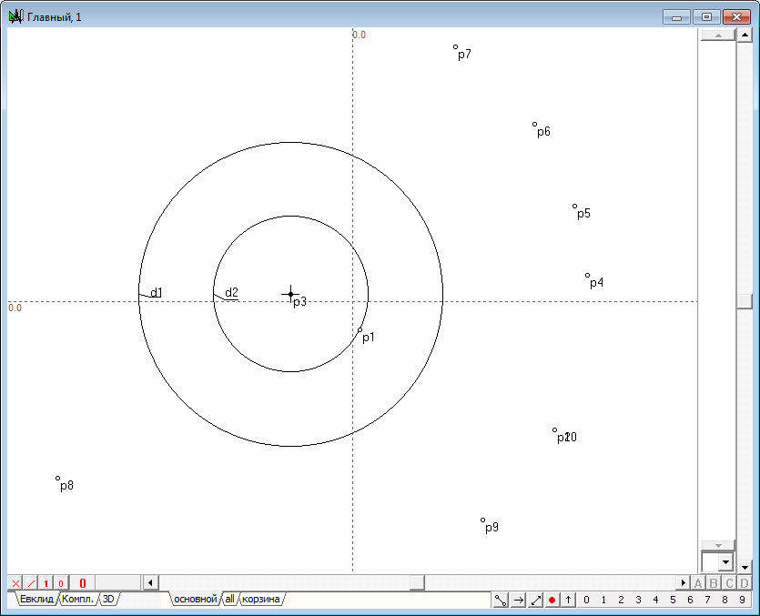
| 8 | In order to fix the intermediate position of the point p2 determined by the position of the point p1, you can use the following technique: select a point p2, and then in the position of interest press on the key with the symbol =. The result of this action is the addition of free point with coordinates equal to the current coordinates of the selected point. Execution of this operation in different positions of the point p1 will allow us to produce an intermediate position of point p2 is represented by a set of additional points.
Fig. 7 |
|
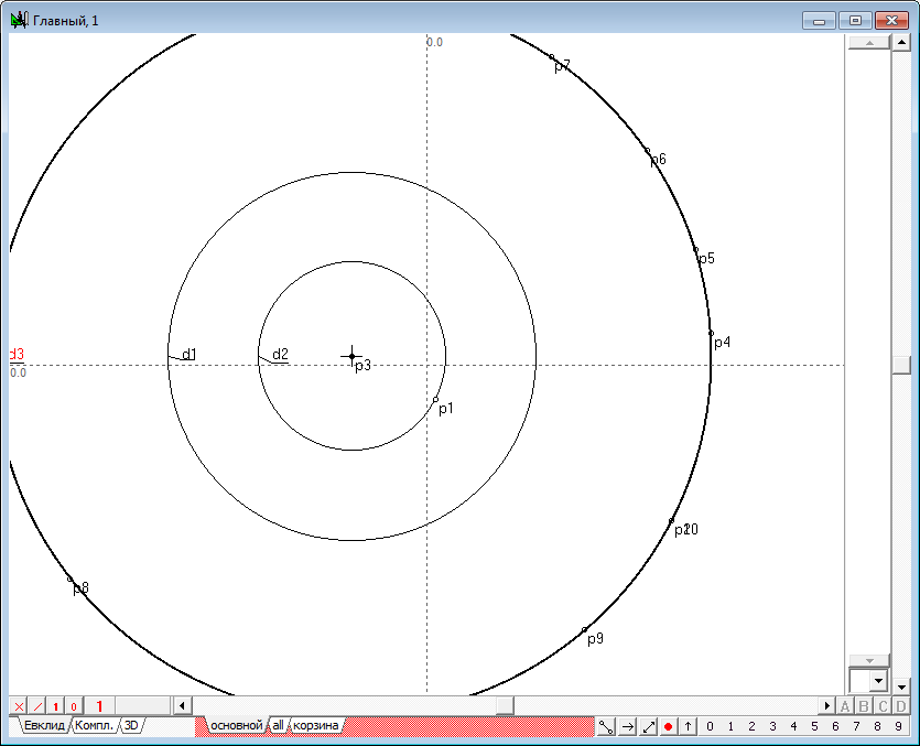
| 9 | The resulting pattern allows us to estimate visually the nature of conversion, and, if necessary, to ensure its "authenticity". So, for example, selecting three points p4, p5 and p6, draw through them a circle, tapping on the key with the Latin symbol g.
Fig. 8 |
|
| 10 | It is clearly visible that all other points lie on a circle formed from what we can infer (or rather guess) that it is concentric with the circumference of the inversion circle are moving in the inversion to concentric circles. Of course, it should be understood that visual interpretation is not strictly a geometric proof of the observed properties. For a proper understanding it is necessary to identify strict logical relationships arising from the interaction of objects of the algorithm. However, the advantage of the proposed experimental method is that a visual interpretation can give the way to finding a logical solution of the problem and significantly increase the confidence of the researcher in the correctness of the chosen path. It is necessary to notice, that the point p1 can be disconnected from the circle d1 in the same way that it join this circle. "Hook" point p1 with the shaper and press on the Shift key. Move the point p1 to the field free of the drawing and release the left mouse button and Shift key too. The point p1 will be redefined as free point with coordinates corresponding to the current cursor position. |
|
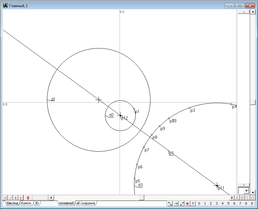
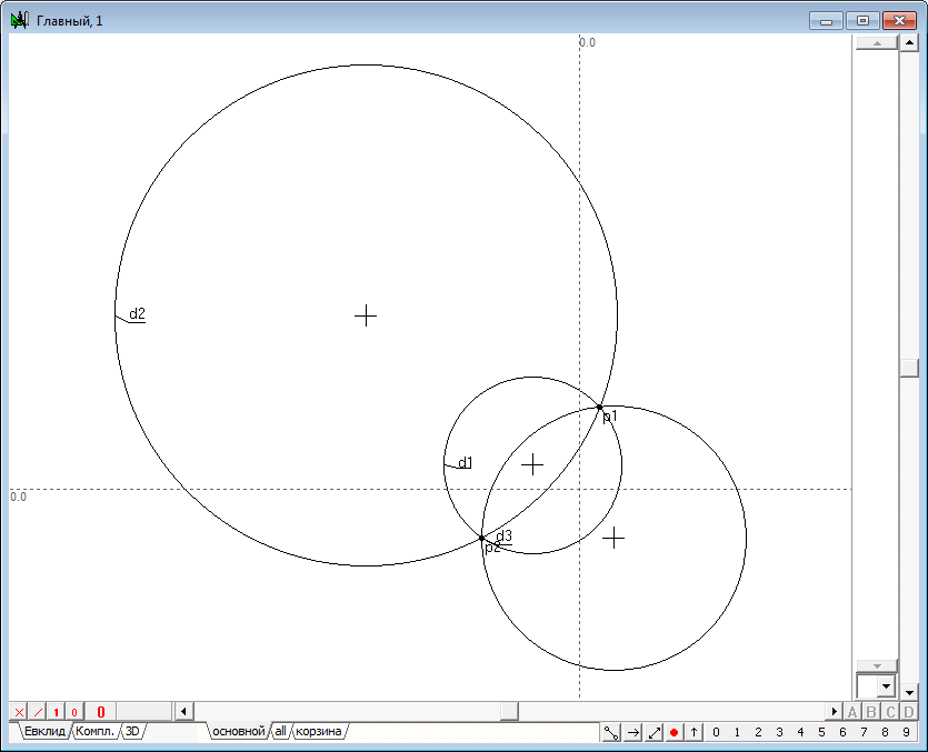
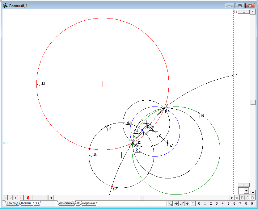
| 11 | Let us study the transformation of inversion in circles that are not concentric with the circle of inversion. To do this, draw in the area drawing a circle and place a point on it, which is to be converted to inversion in its image. Acting on the scheme performed in the previous example, we find that the circumference is converted into another inversion in a circle. The centers of both circles are on a line passing through the center of the circle of inversion.
Fig. 9 |
|
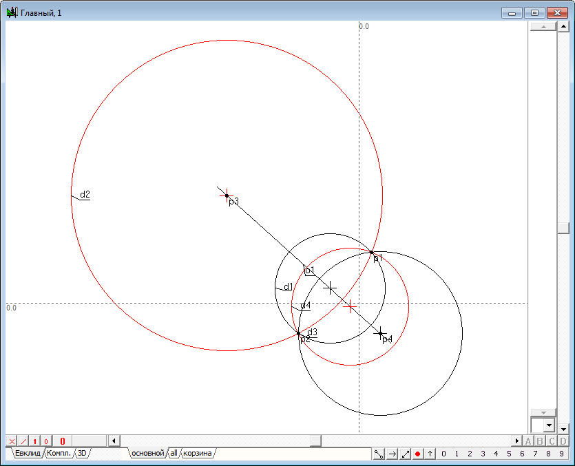
| 12 | Construct the radical axis o2 of the original circle d2 and the image circumference d3. We shall draw a circle orthogonal to the circles d2, d3 and line o1, selecting those objects and pressing on the key with a Latin symbol D (upper case). It is seen from the drawing, that the got circle is perpendicular to the circle of inversion to and radical axis.
Fig. 10 |
|
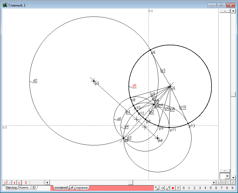
| 13 | Along with the transformation of points the function of the system Simplex Inversion of the object allows the transformation of a circle relative to the circle of inversion. For example, it is easy to see that the circumference d2 is converted into the inversion with respect to the circumference d1 circumference d3. As well as the circle d3 is converted by inversion with respect to the circumference d1 circumference d2. We will consider several remarkable properties related to circles in the transformation of inversion. A circle orthogonal to the circle of inversion is transformed into itself. As well as the circle of inversion is transformed relative to the orthogonal circle into itself, if the latter is considered as a separate circle of inversion. However, this is not true for the dot row that is located on the circle. For example, if you convert the points p8, incident with a circumference d3, relative to the orthogonal circle, the circle of inversion, we find that its image will be incident with a circumference d3, but will not coincide with the point p8. And only the intersection of both circles will move in themselves, being a dual points of the transformation. |
|
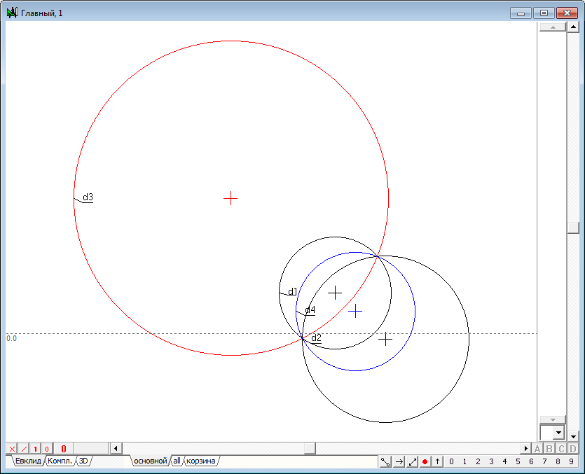
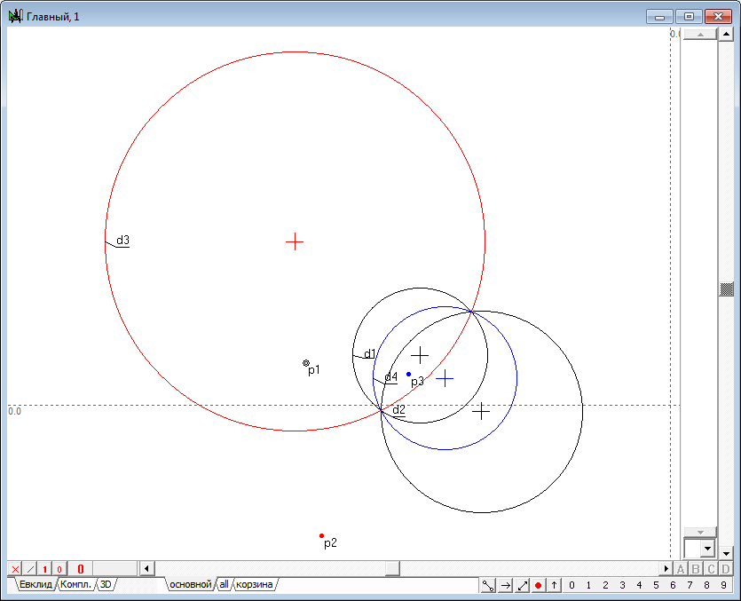
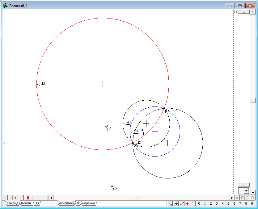
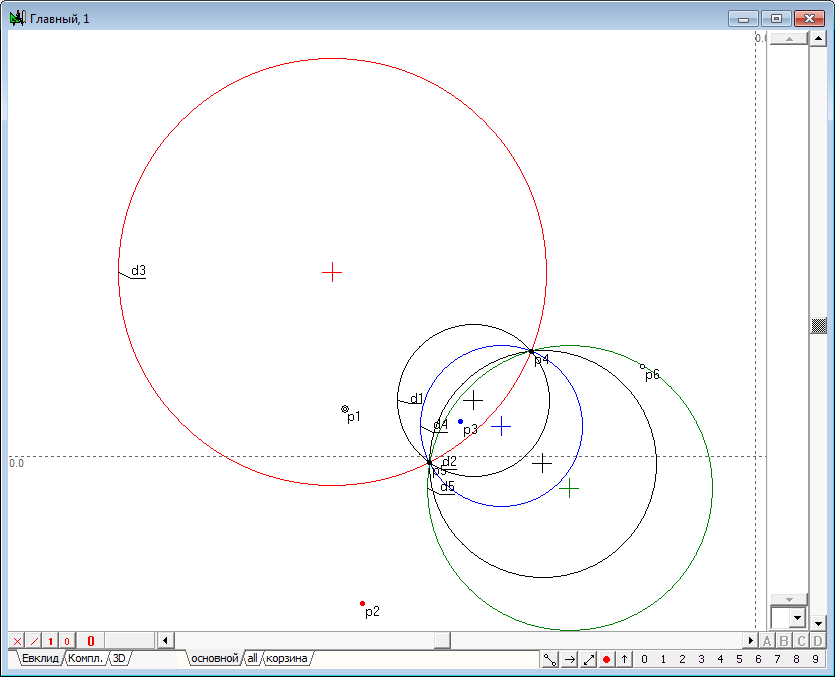
| 14 | Let the initial circumference d1, and the circle of inversion is clearly d2 intersect at points p1 and p2. Lets convert the inversion of the circumference of d1 relative to d2 with obtaining a circumference d3.
Fig. 11 |
|
| 15 | As it can be seen from the drawing, all three circles pass through the points p1 and p2 and, therefore, they are representatives of a circles bundle defined with two centers p1 and p2. We will hold another circumference of the bundle orthogonal to circle of inversion d2. To do this, select the points p1, p2, circumference d2 and press on the key key with a Latin symbol D (upper case). The result of this operation is a circle d4. Being orthogonal to d2, circumference d4 in the transformation of inversion goes into itself. Pay, attention to another remarkable property of the circle. In the same way as the circle d2, circle d4, considered as a distinct circle inversion transforms circles d1 and d3 into each other. Thus, it can be argued that for a couple of circles out on the plane, there exists a pair of orthogonal circles, transforming the original into each other in the transformation of inversion defined on each of the orthogonal pairs of circles. We call these circles of inversions coupled. It should be noted that such circles in the general case, translate the arbitrary point of the plane in two distinct points, between which, however, it reveals a certain geometric relationship. We make a search of this relationship in solving the following problems. All circles shown in the drawing of the are representatives of one bundle of circles with centers being the points of intersection of the two original circles. The first challenge we must address is the problem of finding two circles, which are circles of inversion with respect to two given circles including the case when the original circles intersect explicitly (i.e. have an imaginary intersection point).
Fig. 12 |
|
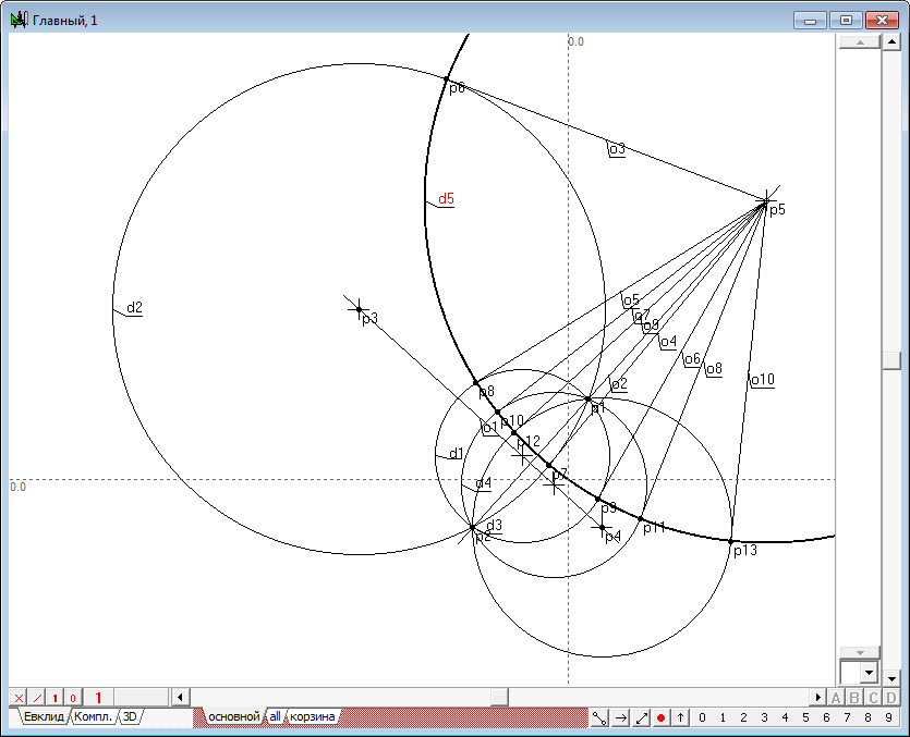
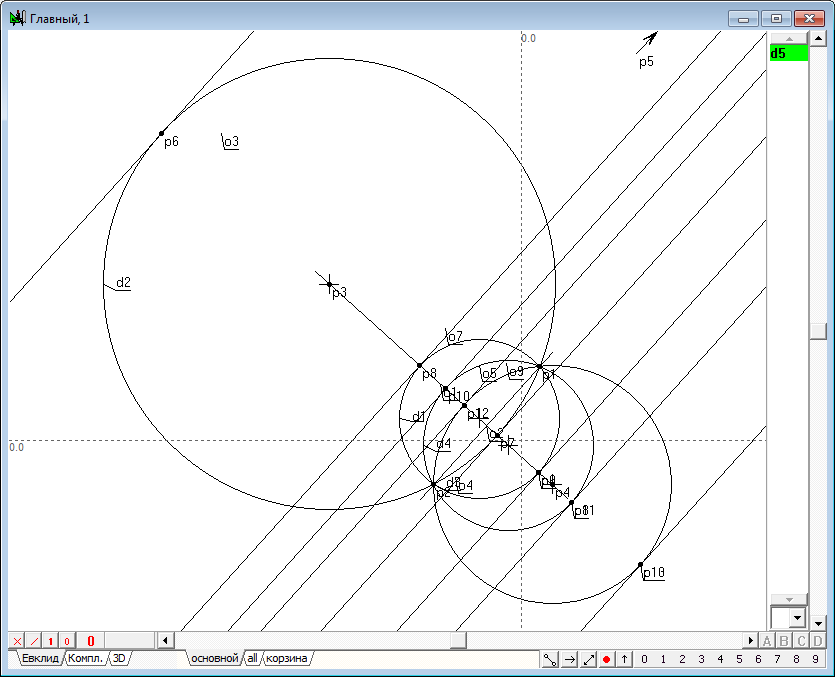
| 16 | Now consider this variant of the mutual arrangement of the original circle and the circle of inversion, in which the original circle passes through the center of the circle of inversion. As mentioned above, the point coinciding with the center of the circle of inversion maps to any of the points of an infinitely distant straight line. Knowing that the inversion transformation is one-to-one except for the case under consideration, we can conclude that any two distinct points through which the original circle is converted into the inversion of two conflicting points. At the same time, the third point coincident with the center of the circle of inversion is ambiguous should go to infinity. Or, in other words, this point must be uniquely mapped to the infinitely remote straight line. Thus, we need to answer the question: what geometric image will be the result of the conversion of the circle passing through the center of the circle of inversion, if he will have to go through two points-plane and any of the infinitely remote points of an infinitely distant straight line. To answer this question we shall start a simple geometric experiment. Select in the plane three mismatched free points, draw a circle passing them (select the three points and press on the key with Latin character g). Two of them are we shall assume as fixed, and the third will begin to move into infinity, and in different directions. Watching the picture, we see that regardless of the direction of movement of the third point to infinity, the circumference begins to look like a staight line. So, we can conclude that regardless of choice of direction to the infinitely distant point follows the original circle in the transformation of inversion is a straight line passing through two fixed points. However, given that the only point of this circle corresponds to an infinitely remote line it should be recognized that the image circle is added including the infinitely remote straight line. This Addendum, which is not usually considered, can be considered we obtained a direct image of the original circle as a "full circle". For example, the result of intersection of a straight line with the circle are the two points. But if any (optional) straight line cross the line-image without taking into account the infinitely remote straight line, we would receive only one point. If the infinitely remote line is taken into account, the result of crossing an arbitrary line with our way gives rise to two points, that leaves us with the exceptions. At the same time and in the reverse transformation invert no exception is not formed: the two circles will intersect in two points, one of which coincides with the center of the circle of inversion, and the other will correspond to the image the actual point resulting from the intersection for more direct and "private parts," obtained the first image. All resulting in the drawing of a circle, including the generalized image-line, have the same radical axis, which passes through the centers of the formed bundle. In fact, the radical axis is nothing but a "private part" of the image of the circle passing through the centers of the bundle of circles and the center of the circle of inversion. Note that a pair of objects a circle-line (in the generalization to the circle) the radical axis is straight line (or rather, its own part). The disclaimer used in the preceding paragraph require further clarification. So, according to one of the properties of radical axis, tangents, dropped from any point incident with the line at any circumference of the bundle have the same length. Therefore, this point is the center of a circle with a radius equal to the length of the tangent, is drawn on any of the circles of the bundle and this circumference is orthogonal to all circles of the bundle.
Fig. 13
Fig. 14 |
|
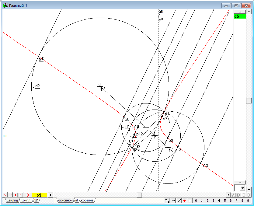
| 17 | Let's move the point p5 to infinity in the direction of line o2. We will observe In this travel by means of change of a circle d5 the presence of another bundle of circles orthogonal to the original bundle. Bringing the point p5 to infinity in the direction of the line o2, down from p5 tangent to the circumference of the original bundle. These tangents form a bundle with an improper center of a bundle of parallel lines. The points of tangency of these circles with the lines bundle will be located on the line o1 (which is the circle in the same sense as image, reviewed in the previous example) passing through the centers of the circles, and this line will be orthogonal to the circles of the original bundle.
Fig. 15 |
|
| 18 | Let's see how to change the picture, if to set up the point p5 to a different direction not coinciding with the direction of the straight o2, moving it at the infinitely remote straight line. Now we can't build neither a line nor a circle that passes through the points of tangency of the bundleof lines to the appropriate circles of the original circles bundle. However, it is easy to see that in this case, the curve of the second order (hyperbola y1 in the drawing) will pass through the touch points. Therefore, we should conclude that the property of the radical axis is to carry the centers of the circumferences of the bundle orthogonal to the given one, occurs only at the part of the circle, "degenerate" into a straight line, which is its "own" part, resulting in the radical axis should be considered as a straight line, not a degenerate circle.
Fig. 16 |
|
| 19 | In that case, if the initial circles do not intersect explicitly (that is, have imaginary intersection point), all the above reasoning must remain in force. However, in this case, one of the circles of inversion becomes imaginary and its image cannot be represented in the drawing directly, it becomes impossible to "lean" on its outline instrumentally. However, methods of geometric modeling implicitly allows to use this object. This possibility is based on the fact that the imaginary circumference or otherwise specified on the drawing indirectly at our disposal an explicit object and is in geometrical relationship with them. The next task will be to find a General algorithm for finding the image point in the inversion with respect to the circumference of any nature - real or imaginary.
Fig. 17 |
|
| 20 | We look for the solution algorithm of the task, breaking it into several stages. First of all, solve the problem of constructing the point in the inversion relative to the circle of inversion, using for this purpose the coupled circle of inversion, and solve this problem first for the case of real result of two circles of inversion intersection. We define two initial circumference d1 and d2, intersecting in two real points.
Fig. 18 |
|
| 21 | Now construct the two conjugate circles of the inversion of d3 and d4 that transform the circle d1 and d2 into each other. To do this, select the circle d1 and d2 and press on the key with Latin character R (in uppercase). Now we will need on the presence of these circles to study their relationship in the operations of finding of image point.
Fig. 19 |
|
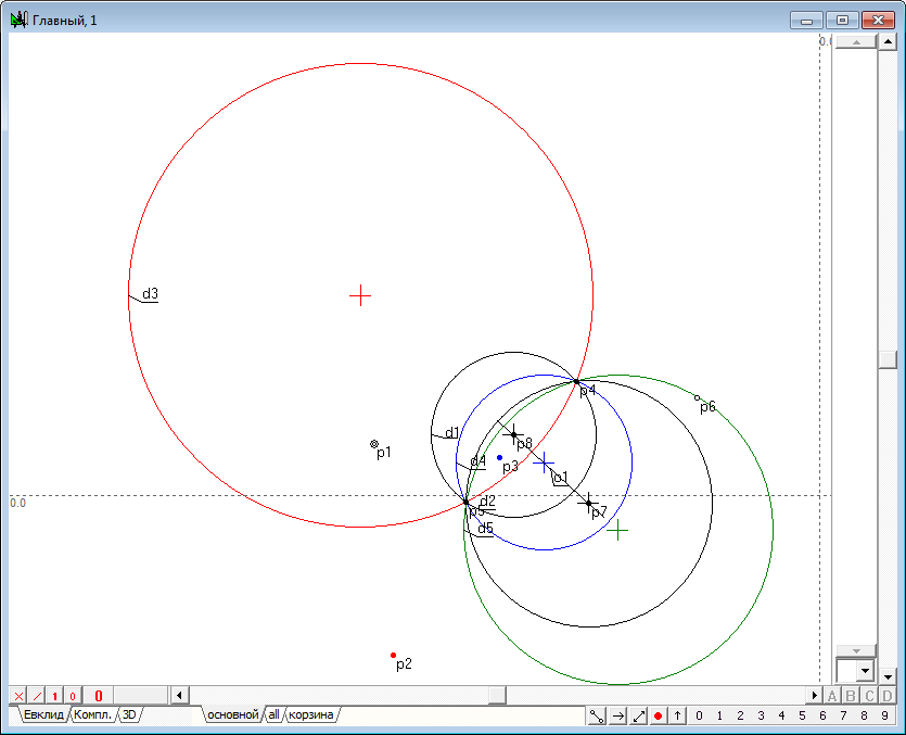
| 22 | Let the point p1 is the original. We transform it into the operations of inversion with respect to a circle d3 first and then respectively to the circumference d4. Get respectively images p2 and p3. To do this, select point p1, then holding down the Shift key, select the circle d3 and press on the key key with the Latin character i. Similarly use the circle d4.
Fig. 20 |
|
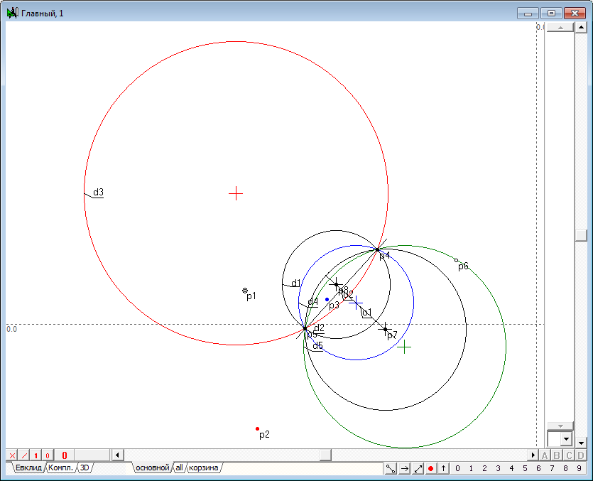
| 23 | Find the centers p4 and p5 of the bundle of circles represented by circles d1-d4. To do this, select the original circle d1 and d2 and press on the keyb with Latin character p.
Fig. 21 |
|
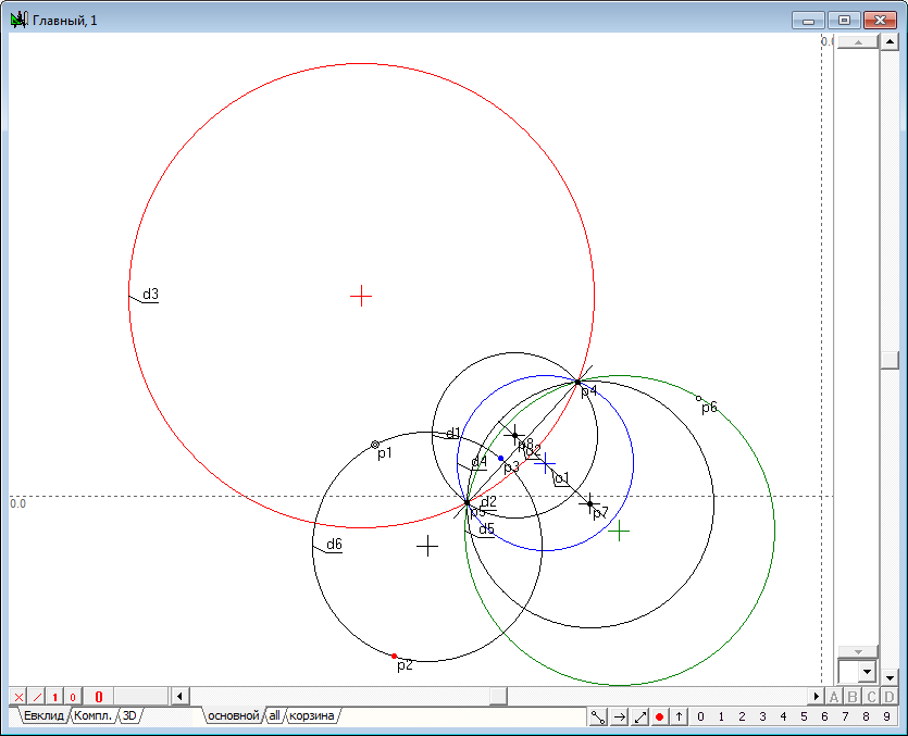
| 24 | Let's make another arbitrary circumference of the bundle. For this use tool Free point placeing cursor on any place of the drawing to assign point p6, and then highlighting with a bundle centers p4 and p5, press on the key with the Latin symbol g.
Fig. 22 |
|
| 25 | Define the axe of bundle - line o1. For this purpose, find the centers p7 and p8 of the circles d1 and d2 by selecting them and clicking on the key with Latin character c. Then for generation of line o1 type on the key with the Latin o.
Fig. 23 |
|
| 26 | Construct the radical axis o2 of the bundle of the circles highlighting the points p4 and p5 and clicking on the keyboard with Latin character o.
Fig. 24 |
|
| 27 | Using the prototype point p1, the radical axis o2, and an additional circle d5, construct the circle d6 passing orthogonally to these objects. To do this, select the objects and press on the key with Latin character D (upper case). Pay attention to the fact that we use a circle d5, despite the fact that our construction has a circumference d1 and d2, by which it would be possible to obtain a similar result. This is done with the intention to show that future algorithms in which the circumference of d1 and d2 will be not specified, the main task of finding points of inversion still will be solved without their participation.
Fig. 25 |
|
| 28 | We see that the circle d6 passes through of the point p2 and p3, which, as we have noted, are the images of the point p1 relative to the circumferences d3 and d4. Now let's try to solve the task to identify the locus of the point p2, knowing the point p3, but without using the circle d3. This task is solved by elementary, drawing a circle d7 passing the bundle centers p4 and p5 and the point p3 and finding its intersection with the circumference d6. To do this, select these points and click on the key with the Latin symbol g. Two of the resulting intersection points is required to choose the one that does not coincide with the point p3.
Fig. 26 |
|
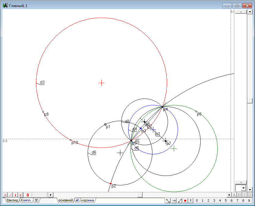
| 29 | The task is solved. However, we will continue our study and show that the same result can be obtained without having the outlines of the circles d3 and d4, not knowing the points p3 and not relying on the circle d1 and d2. All we need is only the possibility to obtain the pair of points incident with a circumference d3, and in the general case, these points do not necessarily have to be real. Generally speaking, such a pair of points can be obtained by the operation of intersection of arbitrary straight line with a circle. In our construction we shall use the assignment of points incident with the object that will not affect the general idea of the algorithm implementation. Set the cursor to any arbitrary place of a circle d3 image, hold down the Ctrl key and click on the left mouse button. This operation will lead to the fact that a point p9 will appear on the circle. Similarly, we construct another point p10.
Fig. 27 |
|
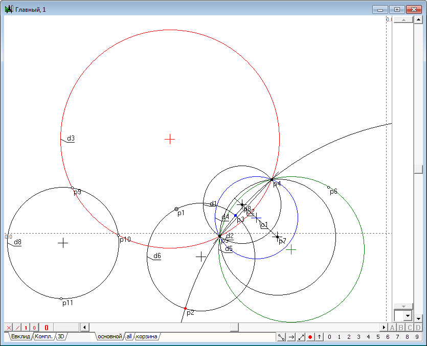
| 30 | Generate the point p11 in any part of the drawing using Free point tool, and then, selecting it together with the points p9 and p10 by press on the key with the Latin character g to construct a circle d8.
Fig. 28 |
|
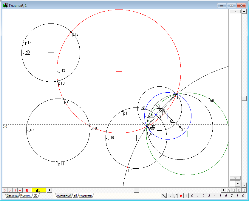
| 31 | Similarly place a couple of points p12 and p13 on the circle, and assign the point p14 in any part of the drawing. Construct the circle d9, passing these points.
Fig. 29 |
|
| 32 | Draw line o3 passing the points p9 and p10, selecting them and pressing the key with Latin o, and then adding to the selected line circles d8 and d9 press on the key with Latin symbol D (upper case) to construct a circle d10, orthogonal to the selected objects. Pay attention to the fact that this circle is also orthogonal to circumference d3, which means that it can be used as a conjugate circle of inversion while the image of the point p1 in relation to the "absent" circle d3.
Fig. 30 |
|
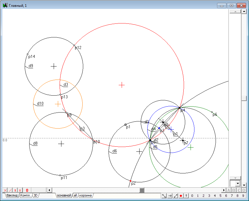
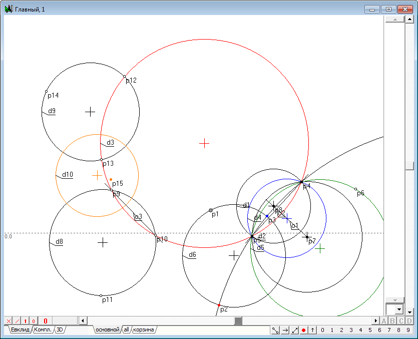
| 33 | We now construct the image p15 of the point p1 in the inversion relative to the circle d10.
Fig. 31 |
|
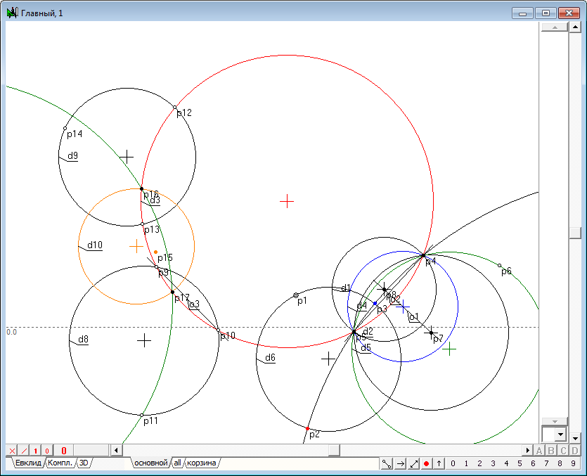
| 34 | Finding the intersection points p16 and p17 of a circle d10with a circumference d3 (highlight d10 and d3 and press the key with Latin symbol p), add to the selection an arbitrary point, for example, p11, draw a circle passing through them by pressing on the key with Latin symbol g.
Fig. 32 |
|
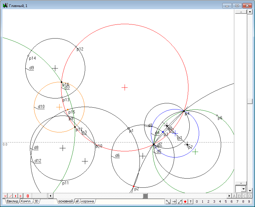
| 35 | Draw a circle d12 passing through p1 and p15 and orthogonal to the circumference d10, by selecting those objects and pressing on the key with symbol Latin D (upper case). It is seen from the drawing, that the circumference d12 has gone through the required point p2. However, its exact geometric position we have not yet determined.
Fig. 33 |
|
| 36 | To complete the solution of the task will shall draw the circumference d13, passing the points p15, p16 and p17. Select points and presson the key with a Latin symbol g.
Fig. 34 |
|
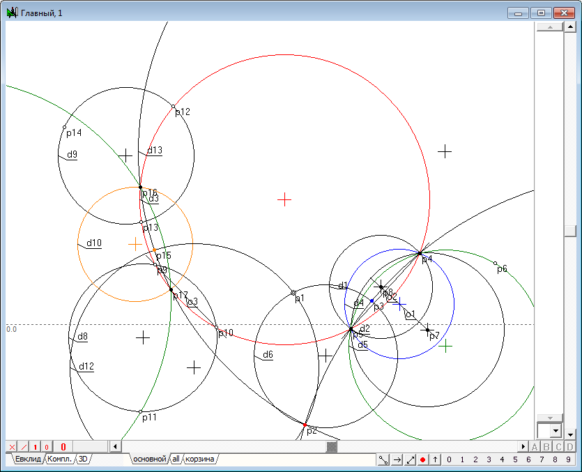
| 37 | Thus, the locus of the image point p1 in the inversion relative to the circle d3 is found by constructing an arbitrary adjoint circle of inversion indirectly. The resulting algorithm allows to formulate and solve the problem of constructing an image point in the inversion, taking into account the case when the circle of inversion does not have an explicit outline, in particular, if the center of this circle is real, the radius is imaginary. Create such an algorithm, execute it in an independent procedure and perform it testing. | |
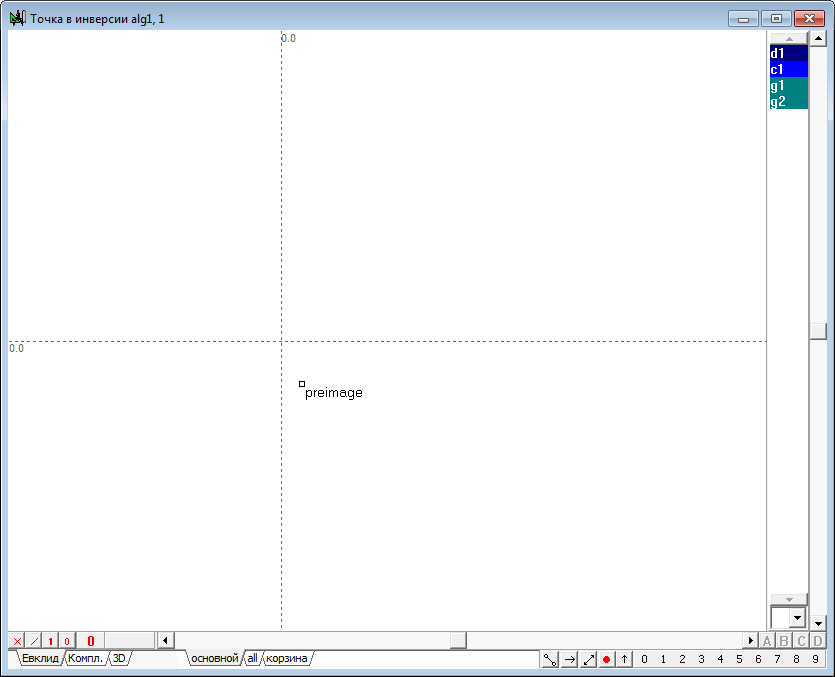
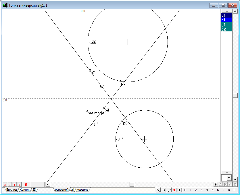
| 38 | Imagine you are given a circle d1 with real center and an imaginary radius. Use the Free point tool to place a preimage point, which will translate in the inversion relative to the circle d1.
Fig. 35 |
|
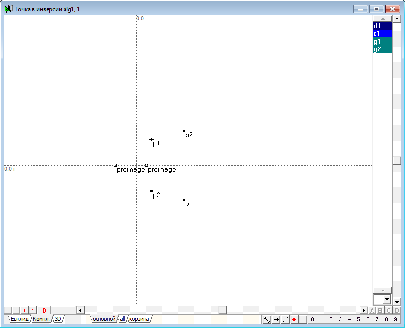
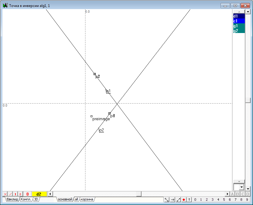
| 39 | Use Free line tool to draw two arbitrary lines o1 and o2 and find points p1, p2, p3, p4 of intersection with a circumference d1. To do this, hold down the Shift key, select the line o1 and label with the name of the imaginary circle d1, and then press on the key with the Latin character p. In the algorithm's window the markers are imaginary points displays in the form of two coincident crossed-out squares, which correspond to the real components of the coordinates of these points. Such markers can be used to highlight imaginary points the same way as selects the indication of the mouse cursor on outlines and images of other geometric objects. In this case, two markers are visually the same because both points have the same real components of the coordinates, but the imaginary components of the coordinates of these points are different, as can be seen, by referring to the Protocol of feature values (called with the key combination Ctrl+O) or by switching to a tab Complex, including the display of objects of the complex plane and located in the left bottom of the window of the algorithm implementation.
Fig. 36 |
|
| 40 | Similar actions will construct points p3 and p4 of intersection of the straight line o2 and the imaginary circle d1.
Fig. 37 |
|
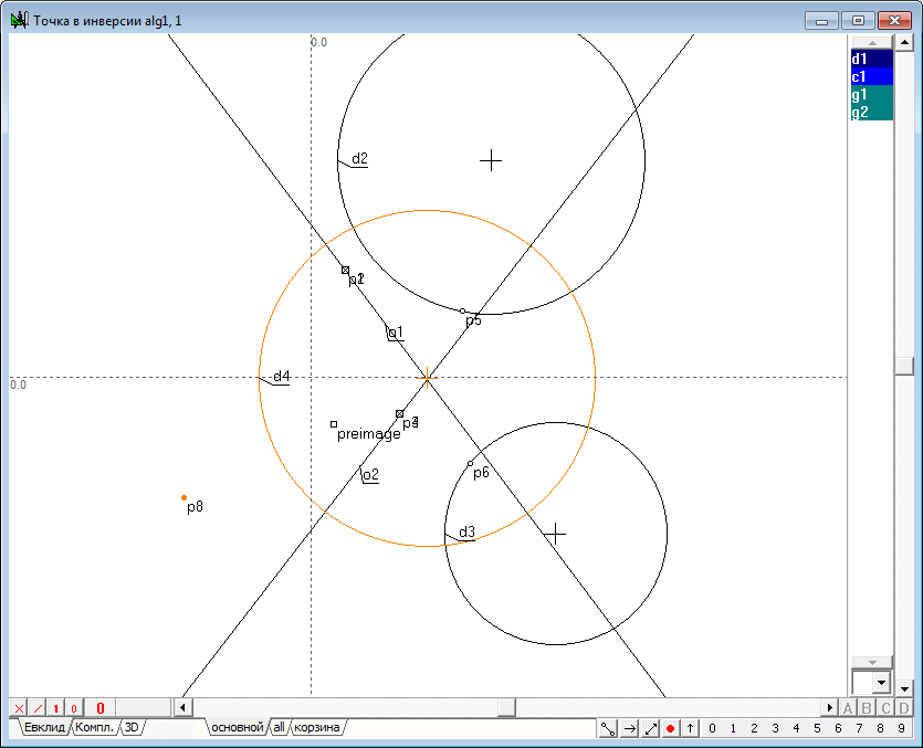
| 41 | We now construct two arbitrary points p5 and p6. Draw circumference d2 passing through p5, p1 and p2 , and circle d3 passing through the points p6, p3, and p4. To assign the circles highlight the corresponding points and press on the key with a Latin symbol g.
Fig. 38 |
|
| 42 | Since the straight line o1 is the radical axis of a pair of circles d1-d2, for the construction of a circle d4, orthogonal to d1, select the straight line o1, circles d2, and d3 and press on the key with the symbol Latin D (upper case). A circle d4 is the conjugate circle of inversion relative to the circle d1.
Fig. 39 |
|
| 43 | Construct point p8, the image of a point "preimage" in the inversion relative to the circle d4.
Fig. 40 |
|
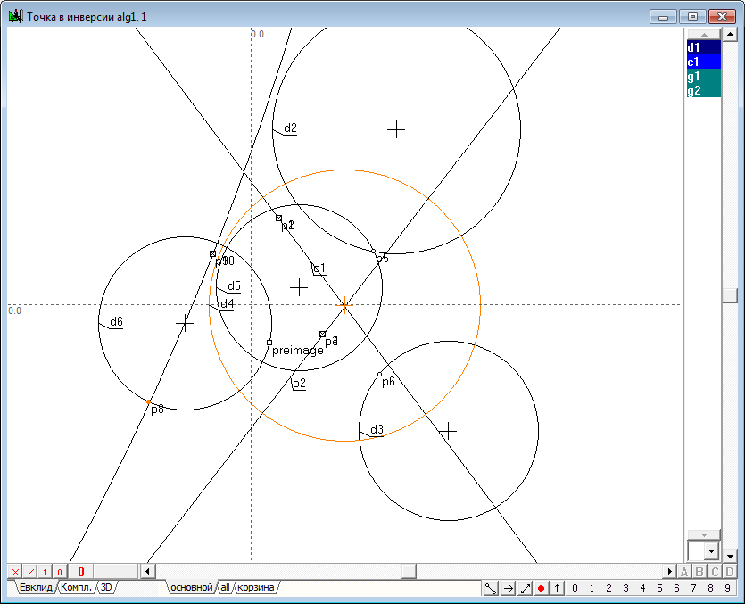
| 44 | Build additional d5 circumference of the bundle of circles set paired circles of inversion d1 and d4. This will find points p9 and p10 of their intersection by selecting the circumference of the d4 and the label of the imaginary circle d1 and then clicking on the key with the Latin symbol p, then adding to the selection point p5 (which, generally speaking, can be arbitrary), click on the button with a Latin symbol g.
Fig. 41 |
|
| 45 | It was shown in the previous example, that the required point is the image point in the preimage of the inversion relative to the circle d1 should be on d6 of the circle passing through the point of intersection of a circle orthogonal to the d4 with the original circle centers of the bundle perpendicular to the circles of this bundle, in particular, to build more of a circle d5. To do this, select the point "preimage", p5 and circumference d5 and click on the key with the symbol Latin D (upper case). Note that using a circle d4 instead of a circle d5 is impossible, because in this case it would be impossible to carry out orthogonal circumference, like the d6, by far.
Fig. 42 |
|
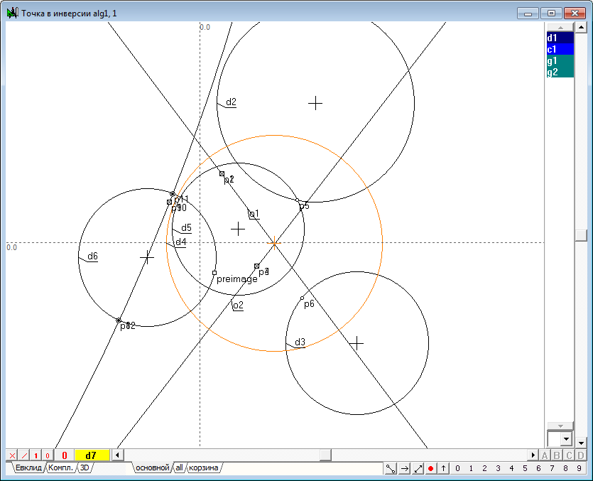
| 46 | The definition of a specific position of the required point perform, drawing the d7 circle through the point p8 and the centers of bundle - points p9 and p10. Select all these points and press on the key with the Latin symbol g.
Fig. 43 |
|
| 47 | We have to find the points p11 and p12 of the intersection of circles d6 and d7, and then to choose as a response is a point that does not coincide with the point p8. To make such a choice, define the distance C1 between the points p8 and p11 by selecting the point and pressing the key with the Latin character l. The result will be determined by the distance between the points p8 and p11, and the label denoting the value of c1 will appear in the list of nonvisual objects.
Fig. 44 |
|
| 48 | Using the Inequality X< Y we define the condition g1 with arguments X: 0.001 (used to specify a small value) and Y: the distance c1. If the distance between the points p8 and p11 will exceed the value of 0.001, then the condition g1 will be true if the points p8 and p11 is almost the same, then the condition is false. The second condition g2 we define a Logical negation function not argument g1. The value of g2 is the opposite (inverse) relative to the value of o1. Final selection of the necessary points is feasible using the function Selector. This function will transfer to the output parameter pnt is the value of point p11 provided to the truthfulness of g1 or p12 subject of the truth of g2.
Fig. 45 |
|
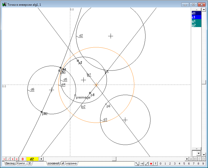
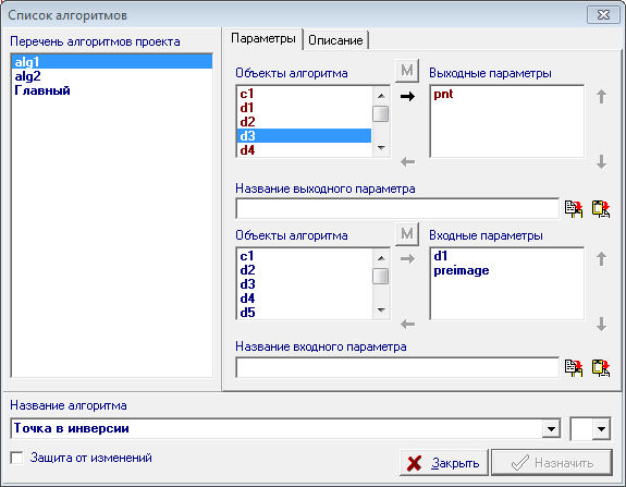
| 49 | We shall specify the circle d1 and a point "preimage" as input parameters of the algorithm. To do this, highlight them and popup the context menu of the implementation of the algorithm Window, select: Assign d1, preimage the input of the algorithm. The parameter d1 will give the name of the Circle of inversion, and parameter preimage the name of the Point. Then open the settings window algorithm with the key combination Alt+A and selecting in the object list of the algorithm responsible for the assignment of output parameters, the object pnt will move it using the Arrow button right to the list of Output parameters. Assign this parameter to the name of the Image. We give the algorithm the name of the Point in the inversion. Since then, the algorithm can be used as a procedure in other algorithms of the project. Fig. 46 |
|
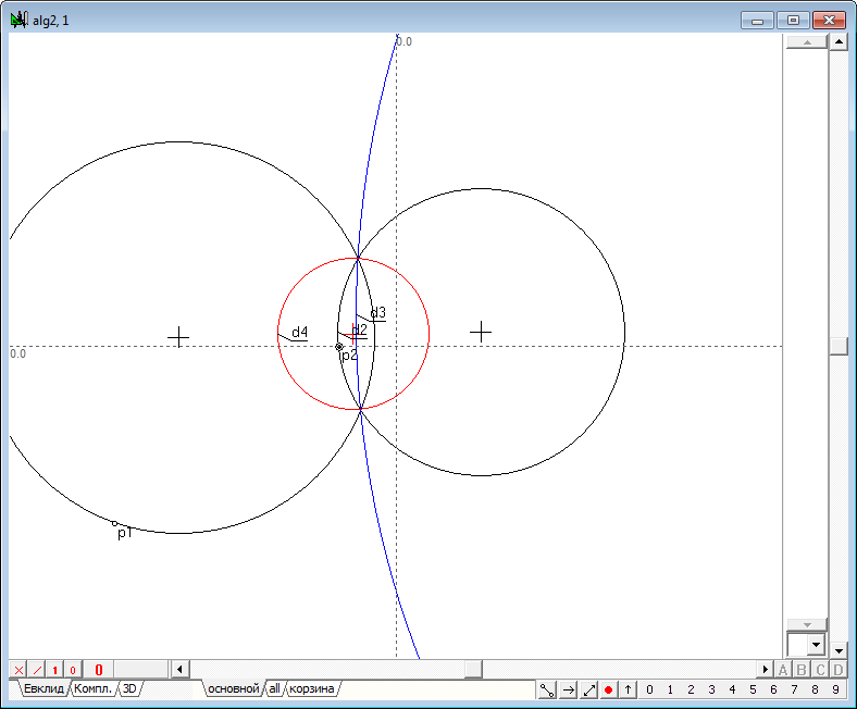
| 50 | To test the correctness and efficiency of the developed procedure to create a test algorithm. Create it using Ctrl+Alt+N will perform the following construction: 1. Build clearly overlapping circles d1 and d2, and then by highlighting them and pressing the key with the Latin letter R (uppercase), construct two circles of inversion of d3 and d4. In order to make it easier to distinguish between them, change their colors with black, for example, red and blue. Then, placing anywhere on the field drawing free point p1, convert it by using the newly developed function by calling it from the menu item Relation/Procedure/Point of inversion. We shall indicate the circumference of d4 as the Circle of inversion, and point p1 as a Point, then press the Enter button and get the desired image point p2. Now you can verify that by moving a shaper point p1 on the circumference of d1, we will obtain the point p2, moving along the circumference d2, which proves the efficiency of our function. If you move a point p1 along the circumference d2, its image in the inversion relative to the circle d4 will move along the circumference d1.
Fig. 47 |
|
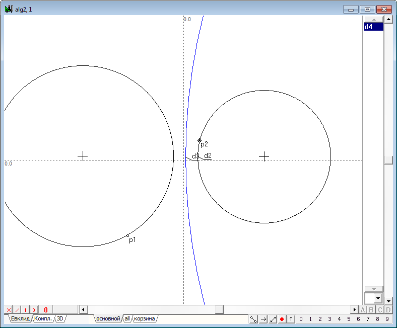
| 51 | If you shift the center of the circle d2 rightward so that a circle d4 will disappear, i.e. go into the imaginary circle, in spite of this inversion operation will still be performed and the displacement of the point p1 along one of the original circle will cause a corresponding displacement of the point p2 along the other of the original circle. When driving point p1 along the second original circle point-image p2 will move along the first original circle, which confirms the correctness and performance of the synthesized algorithm in the case of determining the operation of inversion on the imaginary circle.
Fig. 48
Fig. 49 |
|
| Example (russian version) |